 |
924Board.org
Discussion Forum of 924.org
|
| View previous topic :: View next topic |
| Author |
Message |
Juho

Joined: 03 Oct 2018
Posts: 392
Location: Finland
|
 Posted: Mon Aug 30, 2021 8:02 pm Post subject: 3D Printed Manifolds Posted: Mon Aug 30, 2021 8:02 pm Post subject: 3D Printed Manifolds |
 |
|
Hey
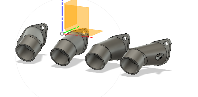
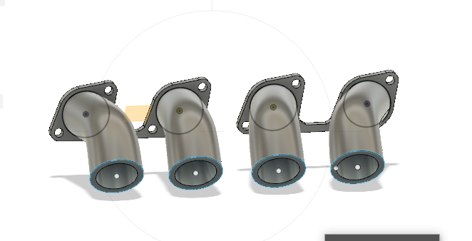
For past 6 months i've been working on 3d printed intake manifolds for bike itbs, the project has been taking so long because i was in army and i didn't have past experience from 3d printing, now i have 4 3d printers all capable of doing high temp plastics and some idea what i am doing.
Im currently at stage of prototyping things, ive done multiple manifolds out of pla and test fitted them on car, i've decided on going short runners at an angle to compensate for the engine's tilt, for hood clearance. I decided to go short runners because this would leave room for BIG cold air plenum for the itbs (some gains hopefully there). im not worried about the manifolds melting without the cold air plenum, i just want more power. The mainfold is currently in rough shape, its the edges are going to be round for better flow.
I've got both manifold for turbo head and na head. With turbo head i used cbr 44mm itbs and with na head 38mm. For the 38mm itbs i have designed full adapter kit for velocity stacks, including adapter collars and the stacks. They are very simple but seem to work on my tests. Have to do some work on the stacks to get optimal length etc etc.
Filament i decided to go with is carbon fiber nylon, It is good up to almost 200C idk if i can take it even further with annealing. Another filament type i was looking at is 3dktop but i didn't believe their claims to it to be good for 200+ temperatures after annealing. And its annealed in 100C so it would change dimensions and warp during it, cf nylon doesen't have this problem.
One of my goal was to make it so theres little as possible post processing with them but theres alot. Manifolds require sanding and the collars require drilling and sanding aswell, but not alot.
My plan is to inject fuel through the cf nylon so it will be intresting to see will it cause any wear on the manifold, (helps to cool them atleast).
If theres someone intrested in testing this im happy to supply you the manifold if you're crazy enough to test this 
I've had bunch of people tell me this wont work that the manifold is just going to melt so no need to tell me that 
In future ill be hoping to make these for other people and possibly for stuff like werber (they would require stupid amount of supports to print) etc.
Ive decided to share this now, because im confident enough that i can get this done.
This weekend i hopefully move on printing out of cf nylon a test runner.
 |
|
| Back to top |
|
 |
Cedric

Joined: 27 Aug 2004
Posts: 2801
Location: Sweden
|
| Posted: Mon Aug 30, 2021 9:33 pm Post subject: |
|
|
Now this is an interesting subject!
I have a prusa mk3S myself, and as you might have seen in my thread im doing quite a bit of designing and printing. For making engine underhood parts I went through many of the high temp materials that are available to be able to compare them. Here is my list:
3dktop for example seems to handle the advertised temps acoording to tests i have seen, but the heat deflection temp which is the value we compare for high temp stiffness is not that special.
https://docs.google.com/spreadsheets/d/1SwUGsPX13aI5OYLEAdHIe6sAIEsenbK4L4K1_puN9jY/edit?usp=sharing
What kind of CF nylon will you use? The problem is not that it will brake and fall of, the issue will be deforming, and not sealing. So its very important to design the sealing and flanges correctly. We test printed parts in high temperature every day in our lab at work, though they are a bit more high spec SLS and MJF printed materials than you can do on a sub300 degree home printer. But temperature and sealing is always a hassle if the design isnt well thought through. Stiffen up the flanges as much as possible, and think through how to spread the load, and how you will clamp the flanges down the best way, there are many options.
I think theres a very large chanse that there would be more performance to get longer runners rather than a larger plenum, but it depends a bit on how you get the packaging together. its easy to try though if you print the runners.
Btw, have you seen https://www.youtube.com/c/MakingforMotorsport/videos
He is already running printed ITBs on a pretty standard CF nylon filament. though he uses the car for weird british car park racing i would guess the heat soak is not that tough, but it seems to work.
If you want any feedback on the design i will gladly help!
_________________
1980 924 Turbo
www.instagram.com/garagecedric/ |
|
| Back to top |
|
|
Juho
Joined: 03 Oct 2018
Posts: 392
Location: Finland
|
| Posted: Mon Aug 30, 2021 11:01 pm Post subject: |
|
|
Yeah i've seen his channel, i started doing the itbs before him but kinda stopped doing it because i thought it was impossible but then saw him doing it with his car and though of it being possible.
Im going to use pa6 cf not pa12cf, i think pa6 will be better even though bit harder to print. I might do to same as making motorsport and replace the stock gasket with the o rings.
Feedback on design is appreciated, im 21 and only been in highschool and really dont have education on 3dmodelling, ive just learned from playing around in fusiojn 360.
I try to make them big layer height and 0.8 nozzle to make them seal well, my friend worries i still have to coat them with something
Also thinking of getting a prusa clone from china, they really are the best.
Im currently using 2 enders and 2 elegoos, all upgraded with all metal hotends and direct drives. |
|
| Back to top |
|
|
Cedric
Joined: 27 Aug 2004
Posts: 2801
Location: Sweden
|
| Posted: Mon Aug 30, 2021 11:21 pm Post subject: |
|
|
| Juho wrote: | Yeah i've seen his channel, i started doing the itbs before him but kinda stopped doing it because i thought it was impossible but then saw him doing it with his car and though of it being possible.
Im going to use pa6 cf not pa12cf, i think pa6 will be better even though bit harder to print. I might do to same as making motorsport and replace the stock gasket with the o rings.
Feedback on design is appreciated, im 21 and only been in highschool and really dont have education on 3dmodelling, ive just learned from playing around in fusiojn 360.
I try to make them big layer height and 0.8 nozzle to make them seal well, my friend worries i still have to coat them with something
Also thinking of getting a prusa clone from china, they really are the best.
Im currently using 2 enders and 2 elegoos, all upgraded with all metal hotends and direct drives. |
Heres another one you maybe have looked at, he do a kind of sealant https://www.youtube.com/watch?v=zIVduZnAFRg&t=2120s , you can also coat them in some kind of epoxy if needed, it shouldnt be a big hurdle.
I would start out with a smaller nozzle, just to get better representation of the geometry, 0.6 is pretty large already if you want to do details, decent radiuses etc. But nozzles are cheap, so you can try them all 
O-rings are good, but sometimes not so easy with printed parts since they arent perfectly smooth, you can use some kind of sealant or do some polishing to get the surface smoother. A smooth flat surface with a fluid sealant can work aswell, but you need half decent clamping force to make it work.
There are many versions of PA6 and 12, but it should be a good base material to try. I like prusament PC-blend (not hydroscopic and fairly easy to print), i will try to print some high temp parts in the PC-Blend CF material ( I have a roll but havent tried it ye) soon i hope.
_________________
1980 924 Turbo
www.instagram.com/garagecedric/ |
|
| Back to top |
|
|
Juho
Joined: 03 Oct 2018
Posts: 392
Location: Finland
|
| Posted: Mon Aug 30, 2021 11:29 pm Post subject: |
|
|
Seen that video, i think he did that to make the parts fuel resistant, i tried getting that stuff but it didnt seem to be available to consumers.
https://eu.polymaker.com/product/polymide-pa6-cf/
Gonna use this |
|
| Back to top |
|
|
Cedric
Joined: 27 Aug 2004
Posts: 2801
Location: Sweden
|
| Posted: Tue Aug 31, 2021 5:10 am Post subject: |
|
|
That will probably work very well, but I think the design will be crucial for the success here. do many iterations in cheaper materials first and try and optimise the design as much as possible. A fun project
Dont forget to dry the filament thouroghly, nylons need to be dry, but you probably know that very well.
_________________
1980 924 Turbo
www.instagram.com/garagecedric/ |
|
| Back to top |
|
|
Juho
Joined: 03 Oct 2018
Posts: 392
Location: Finland
|
| Posted: Tue Aug 31, 2021 2:02 pm Post subject: |
|
|
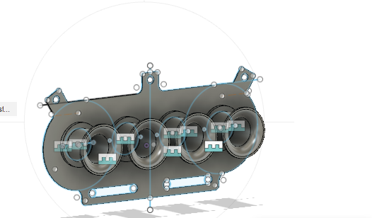
| I need to find a better way to model it, to this point ive just modelled it by using loft tool and there must be a better tool for it that i dont know of |
|
| Back to top |
|
|
gegge

Joined: 27 Jul 2007
Posts: 1124
Location: Sweden
|
| Posted: Tue Aug 31, 2021 5:50 pm Post subject: |
|
|
While your at it, yes longer runners and please be advised that the runners shouldn´t go straight out from the head by 90 degrees. The inlet is inclined and the runners should be more or less horisontal. Look at the original drawings or flow inprovment threads at this forum. I have posted a lot in them. Yes, the ports in head are funny looking...
The tuning of the runners depend on several things like duration of the cam, volumetric efficency and target rpm. But if you model something like 330-370mm from valve to trumpet you´re in the ballpark according to PIPEMAX.
EDIT: Correction, the 931 ports are more straight than 924 ones. The optimal angle for a printed manifold differ therefore.
_________________
Carl Fredrik Torkildsen
924 turbo -81 Carrera GT RESTOMOD
924 turbo -80 Dolomite De Luxe
924 -85 DP kit, BBS RS, M030 and tuned engine
924s -86 Black on black turbo with Fuchs |
|
| Back to top |
|
|
Juho
Joined: 03 Oct 2018
Posts: 392
Location: Finland
|
| Posted: Tue Aug 31, 2021 7:23 pm Post subject: |
|
|
| gegge wrote: | While your at it, yes longer runners and please be advised that the runners shouldn´t go straight out from the head by 90 degrees. The inlet is inclined and the runners should be more or less horisontal. Look at the original drawings or flow inprovment threads at this forum. I have posted a lot in them. Yes, the ports in head are funny looking...
The tuning of the runners depend on several things like duration of the cam, volumetric efficency and target rpm. But if you model something like 330-370mm from valve to trumpet you´re in the ballpark according to PIPEMAX.
EDIT: Correction, the 931 ports are more straight than 924 ones. The optimal angle for a printed manifold differ therefore. |
havent though about flow that much, only hood clearance, i had these issues with danst carb manifold, Could you give info about making the manifold flow well, old posts are hard to dig up |
|
| Back to top |
|
|
Juho
Joined: 03 Oct 2018
Posts: 392
Location: Finland
|
| Posted: Tue Aug 31, 2021 11:38 pm Post subject: |
|
|
| If anyone has any tips on the shape or modelling it in fusion 360, it would be greatly appreciated |
|
| Back to top |
|
|
Juho
Joined: 03 Oct 2018
Posts: 392
Location: Finland
|
| Posted: Thu Sep 02, 2021 2:56 am Post subject: |
|
|
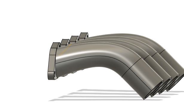
Longer runners |
|
| Back to top |
|
|
safe

Joined: 18 Mar 2017
Posts: 698
Location: Sweden
|
| Posted: Thu Sep 02, 2021 10:30 pm Post subject: |
|
|
As for heat resistance. The 964 used plastic manifolds bolted to the heads, I think an air cooled head will be more toasty than any water cooled.
Over time there was an tendency for the intake to collapse a bit, I think it was only common ABS.
Earlier 911s had a phenolic spacer between the head and aluminium manifold, to prevent heat from soaking up into the manifold. Maybe you can do something similar.
_________________
/Magnus, Stockholm Sweden
=======================
Porsche 924 -79 NA, EFI and Turbo.
Porsche 931 -79
Porsche 911 -77, 3.2 Targa
Porsche 911 -69, 3.6, Coupe |
|
| Back to top |
|
|
Juho
Joined: 03 Oct 2018
Posts: 392
Location: Finland
|
| Posted: Thu Sep 02, 2021 11:24 pm Post subject: |
|
|
| safe wrote: | As for heat resistance. The 964 used plastic manifolds bolted to the heads, I think an air cooled head will be more toasty than any water cooled.
Over time there was an tendency for the intake to collapse a bit, I think it was only common ABS.
Earlier 911s had a phenolic spacer between the head and aluminium manifold, to prevent heat from soaking up into the manifold. Maybe you can do something similar. |
Very nice input! ive already found a good material for this, and shouldnt be too hard to make |
|
| Back to top |
|
|
kondzi

Joined: 02 Jul 2018
Posts: 494
Location: Poland/EU
|
| Posted: Fri Sep 03, 2021 12:32 am Post subject: |
|
|
911 aircooled CHT shows 160-190 celsius normally, but there are heat insulation washers inbetween. The other thing is this is different type of plastic obviously, designed for durability, not for ease of 3D printing
_________________
---
Konrad
'89 951 US
'88 Mustang 5.0 LX Convertible (factory specs)
'84 911 Carrera 3.2 RoW (factory specs)
'81 931 RoW (TBD)
'81 Ford Capri 2.8i (factory specs)
'79 Ford Capri 2.9 (heavily modded) |
|
| Back to top |
|
|
safe
Joined: 18 Mar 2017
Posts: 698
Location: Sweden
|
| Posted: Fri Sep 03, 2021 1:05 am Post subject: |
|
|
| kondzi wrote: | | 911 aircooled CHT shows 160-190 celsius normally, but there are heat insulation washers inbetween. The other thing is this is different type of plastic obviously, designed for durability, not for ease of 3D printing |
Yes, the 3.2 has insulation between,the aluminum head and aluminum manifold.
But the 3.6 doesn't, not with the plastic manifold anyway.
_________________
/Magnus, Stockholm Sweden
=======================
Porsche 924 -79 NA, EFI and Turbo.
Porsche 931 -79
Porsche 911 -77, 3.2 Targa
Porsche 911 -69, 3.6, Coupe |
|
| Back to top |
|
|
|
|
You cannot post new topics in this forum
You cannot reply to topics in this forum
You cannot edit your posts in this forum
You cannot delete your posts in this forum
You cannot vote in polls in this forum
|
Powered by phpBB © 2001, 2005 phpBB Group
|

