| View previous topic :: View next topic |
| Author |
Message |
JasonK
Joined: 01 May 2014
Posts: 28
Location: Detroit, MI
|
 Posted: Wed May 14, 2014 1:48 am Post subject: Red '79 Posh924 Posted: Wed May 14, 2014 1:48 am Post subject: Red '79 Posh924 |
 |
|
Greetings Everyone,
First question:
Can someone verify sparkplug wire positions on the distributor?
Fuel Test Kit Refs:
Hoffman CIS Test Kit
DIY CIS Test Kit
So I'm working on this car, it starts but sputters out within a minute. Cannot rev past about 2k. So far i've cleaned out the gas tank & tested most of the fuel system. My injectors aren't perfect but something's coming out at a potentially acceptable rate. My fuel pressure is too high, 75 psi cold regulated. I cannot test system pressure (M12x1.5 on order) but I assume it's about the same, assuming clogged or stuck control pressure regulator (haynes p78).
Just removed the Auxiliary Air Regulator, it looked barely open but apparently that's normal. Tested good! Timing is next on my list after the CPR.
I actually have two of these and plenty of spare parts, happy to help anyone I can. i have spare time since i'm between jobs, hopefully that changes soon! Then I'll have cash but no time to work... I plan to create new threads for the White '78 and maybe one for parts but for now i'll just be here.
Thanks for any help, will follow up. |
|
| Back to top |
|
 |
fiat22turbo

Joined: 18 Jan 2006
Posts: 4040
Location: Portland, OR
|
| Posted: Wed May 14, 2014 1:51 am Post subject: |
|
|
Firing order is 1342 and when the engine is at TDC, the rotor should be pointed at number one in the distributor cap, which will establish the starting point for the plug wires.
From there you 'll need to get it idling and warmed up so you can adjust the pressures and verify ignition timing.
_________________
Stefan
1979 924 Carrera GTS (clone-ish)
1988 944 Turbo S (Silver Rose) |
|
| Back to top |
|
|
JasonK
Joined: 01 May 2014
Posts: 28
Location: Detroit, MI
|
| Posted: Wed May 14, 2014 1:52 am Post subject: |
|
|
| PS. Special thanks to Peter for helping me setup the account, some stuff doesn't quite work the same from my phone here... |
|
| Back to top |
|
|
ideola

Joined: 01 Oct 2004
Posts: 15550
Location: Spring Lake MI
|
| Posted: Wed May 14, 2014 4:42 am Post subject: |
|
|
You have to make sure the leads are on in the correct order. The distributor rotates in a CLOCKWISE fashion. Set the engine at TDC using the dimple on the back side of the cam sprocket. Remove dizzy cap. Note where the rotor is pointing. Put the cap back on and rotate the dizzy one way or the other such that the rotor would be pointing directly at one of the plug terminals on the cap. Starting with that plug terminal, connect that plug wire to the #1 cylinder. Now go to the next plug terminal in a CLOCKWISE rotation on the cap. Connect that to the #3 cylinder. The next CLOCKWISE terminal goes to #4, and the last one to #2. If you have them installed backward at the dizzy cap (i.e. in reverse or counterclockwise rotation) the car will run, but only on two cylinders, as #3 and #2 will be firing in opposite order.
_________________
erstwhile owner of just about every 924 variant ever made |
|
| Back to top |
|
|
pmcaya2

Joined: 24 Nov 2005
Posts: 191
Location: Scio, NY USA
|
| Posted: Wed May 14, 2014 3:09 pm Post subject: |
|
|
It's worthwhile to check the timing belt alignment as Ideola suggests. You might want to check out my post on belt alignment in the tech section.
One other thing you might want to check is the seal on your air duct between the fuel distributor and intake. Any vacuum leak results in poor performance since the system depends on vacuum to lift the distributor plate. |
|
| Back to top |
|
|
JasonK
Joined: 01 May 2014
Posts: 28
Location: Detroit, MI
|
| Posted: Wed May 14, 2014 11:05 pm Post subject: |
|
|
Thanks Ideola, appreciate your patience & attention to detail.
Hi caya, under HowTo with a search I did find this thread .
I am also aware of another tech section with some good info and a useful faq. After all this research I think at a point we deserve a degree or maybe some type of certificate. |
|
| Back to top |
|
|
pmcaya2
Joined: 24 Nov 2005
Posts: 191
Location: Scio, NY USA
|
| Posted: Wed May 14, 2014 11:57 pm Post subject: |
|
|
| You found the correct thread -"how to" section. Thanks & good luck. - Peter |
|
| Back to top |
|
|
bradelporsche

Joined: 29 Mar 2008
Posts: 51
Location: VA
|
| Posted: Fri May 16, 2014 10:06 pm Post subject: |
|
|
| Is it possible to have the cam timing 180 degrees off? Will it run? |
|
| Back to top |
|
|
fiat22turbo
Joined: 18 Jan 2006
Posts: 4040
Location: Portland, OR
|
| Posted: Sat May 17, 2014 1:36 am Post subject: |
|
|
Yes, it can run. Poorly.
_________________
Stefan
1979 924 Carrera GTS (clone-ish)
1988 944 Turbo S (Silver Rose) |
|
| Back to top |
|
|
pmcaya2
Joined: 24 Nov 2005
Posts: 191
Location: Scio, NY USA
|
| Posted: Sat May 17, 2014 12:39 pm Post subject: |
|
|
It is possible to be 180 out. In my timing belt alignment procedure from the "how to" section in step #1 you can verify that the #1 piston is at TDC by inserting a pencil or dowel down the spark plug hole. Both valves should also be closed. (you should also be able to see the piston with the right light.)
Keep us posted on your progress - Peter |
|
| Back to top |
|
|
JasonK
Joined: 01 May 2014
Posts: 28
Location: Detroit, MI
|
| Posted: Wed May 21, 2014 8:59 pm Post subject: |
|
|
Ok not done yet but I've learned a lot, I found my timing marks and I understand how the "dizzy" works. The wiring was always a mess so I'm now thinking this was the original culprit.
Someone removed the 7pin inline connector near the coil, at this point anything I do here will be an improvement. I'll continue to work when I have time and follow up with results.
Ref Haynes Pic 1.4.16 "multiple lead plug" |
|
| Back to top |
|
|
JasonK
Joined: 01 May 2014
Posts: 28
Location: Detroit, MI
|
| Posted: Thu May 22, 2014 1:03 pm Post subject: |
|
|
Edits 5/22/2014
Ok I got almost everything back together, i do have some electrical questions referencing Haynes 11.11 p258. I'm working on the wires from inline T7a and could use some help identifying the various temp switches on tracks a8, a10, a21, d33, and e9.
On a '79 the YeRe wire goes from ReBk to the Supplementary Start Valve (SSV) a10. Is this a cylinder on the side of the airbox, can someone explain this?
I don't think it's present on a '78 and I do not see the Air Flow Sensor plug (pic 3.31.7) on my air sensor unit.
I see Coolant Temp Sensor and Thermo Time Switch on rear coolant flange p66, is that round thing in pic 2.21.9 my Oil Pressure Sender Unit? There is also a Coolant Sensor on p106 judging by the short tube with two electrical connections, I seem to have the 1977.5 Temp Switch... however my vehicle is a '79 (Insert PO reference here).
The Radiator has a Thermo Switch on p60 which is none of these. I was hoping this would be more obvious, thanks for any advice or references. Most of the wires appear to be correct, but I'd appreciate specific appearance & locations to ID these components. |
|
| Back to top |
|
|
larchie
Joined: 19 Jun 2003
Posts: 297
|
| Posted: Fri May 23, 2014 12:42 am Post subject: |
|
|
Unfortunately, I couldn't follow all your questions -- I looked at two different editions of the Hanes manual and the Porsche Workshop Manual and your references didn't match up very well. But hopefully the following might be of help.
On the 1979 Model an electric solenoid was introduced to help warm start behavior -- this is the same as the supplementary start valve. The valve is connected to the control pressure line a in Fig. 1 Solenoid.

Fig. 1 Solenoid
The solenoid is in the lower left corner of Fig. 1 with line b at the top and two wires coming out of the bottom.
The solenoid (supplementary start valve) is controlled by a temperature switch which is installed in the coolant return line from the cylinder head here in the center of Fig. 2 Temperature Switch.

Fig. 2 1979 Temperature Switch
The coolant line sensors at the back of the engine on the 1981 924 look like this:

Fig. 3 Temperature Sensors 1981 924 (credit: Ian89C4)
Sensors left to right in Fig. 3: (1) coolant temperature switch PN 047 131 851 D, (2) thermo vacuum valve PN 058 131 851 A, (3) acceleration enrichment temperature switch PN 047 131 851 D.
For the different sensor configurations for the 1976-1979 Porsche 924 see the identity numbers 28, 29, 30, 36, 37, 38 and 39 in the Porsche 924 924 exhaust gas recirculation diagram from AutoAtlanta.
Finally, here's what the T7a connector wiring looks like for the 1978 Porsche 924 current flow diagram from the factory Porsche 924 Workshop Manual:
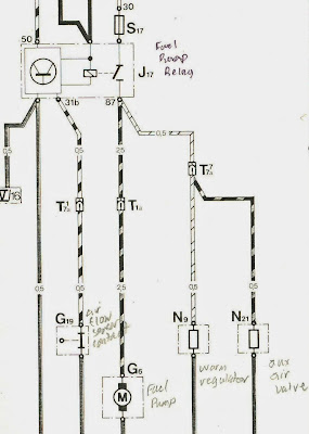
1978 Porsche 924 Fuel Pump Wiring
Hopefully, this matches the page you refer to in your published edition of Hanes for the current flow diagram of the 1977 1/2- 1978 924. |
|
| Back to top |
|
|
JasonK
Joined: 01 May 2014
Posts: 28
Location: Detroit, MI
|
| Posted: Fri May 23, 2014 2:43 am Post subject: |
|
|
Your autoatlanta link is great, my car has 38&39! Yes your diagram mostly matches Fig 11.9a in my books, however the wires in my diagrams have color codes as text.
I may not have been clear, I'm looking at 1979. Fig 11.11 letters 'a' through 'e' in my books, it appears the diagrams are no longer labled with roman numerals however those still do appear in the key and where wires are shared/jump between diagrams. So the WUR a20 is I20 in the key and d33 is IV33. The Key page is quite useless on the 1979 diagrams since the references were replaced with text on the diagrams.
The word solenoid may help answer my first question, though it appears to have only one fuel-line whereas mine has two banjo bolts. I will research the solenoid and upload some pics. |
|
| Back to top |
|
|
larchie
Joined: 19 Jun 2003
Posts: 297
|
| Posted: Fri May 23, 2014 4:05 am Post subject: |
|
|
Yes, the solenoid or supplementary start valve (it's also called the hot-start valve in some literature) has two fuel lines connected on the 1979.
Here's the schematic of a 1981 with the solenoid (SSV) labeled as number 7 (vertical unit bottom 1/3 of picture above and left of the fuel distributor and lines coming in via washers numbered 15 on top and sides of the solenoid (CSV).

Fuel Lines 1989 (credit leadfoot)
Here's a better image of the solenoid (SSV) from a 1980 924:

Solenoid or Supplementary Start Valve 1980 924 (credit rkn)
The wires on my 1979 924 to the solenoid or Supplementary Start Valve are BR/WH and YE/RE, but in the Porsche 924 Workshop Manual for 1979, and in Hanes, for 1979-1980, the Supplementary Start Valve wires are labeled BK/GN and BR. So, I am puzzled when you state:
| JasonK wrote: | | On a '79 the YeRe wire goes from ReBk to the Supplementary Start Valve (SSV) a10. |
I don't see this wiring in any of the current flow diagrams I have -- i.e., Hanes 1981 and 1984 or the Porsche factory 924 Workshop Manual or on my '79 in the garage. |
|
| Back to top |
|
|
|

