 |
924Board.org
Discussion Forum of 924.org
|
| View previous topic :: View next topic |
| Author |
Message |
Cedric

Joined: 27 Aug 2004
Posts: 2608
Location: Sweden
|
 Posted: Thu Dec 03, 2020 6:18 pm Post subject: Posted: Thu Dec 03, 2020 6:18 pm Post subject: |
 |
|
| jazz guy wrote: | | Cedric wrote: | | If you can aim for a twinscroll charger, it will make it much less knock sensitive. It made a big difference in EGT on joakims engine when he did that change, and makes it possible to accept more cam duration, you should at lest have a "stage 1" cam I think. For the head some rework of the inner radius and some filling in some areas would be good, do you plan on DIY or let an experienced head porter do it? |
I'll leave the actual porting to a pro. I have a decent amount of engine building experience but not in head porting. I do want to have a firm concept and plan of attack in mind before I agree to any material being removed, so I've been digging into research on the topic. Still learning.
Thanks for your thoughts on a twinscroll setup. I'll be fabricating a manifold, so building it for twinscroll shouldn't be much more work. I guess it makes sense that it raised the detonation level on Joakim's engine. Less back flow/cylinder contamination when intakes are opening. Might also allow a larger overlap cam to function better in a turbo engine? I'm really not sure how far I can go on cam overlap and not give up too much low end.
| Cedric wrote: | Its always fun with more tuned 931s, there are very few in the world in that gang so it would be fun if you would join in  |
True that! I've always thought these cars would be a hoot with horsepower in the mid-300's. Now I'm fixing to find out! |
Yes, twin scroll drastically reduces the cross talk between the cylinders. Even if you have low mean pressure in the exhaust manfold (like in joakims case) if you look at it in a crank angle resolved pressure trace you will see that you have pressures interacting while one cylunder try to evacuate the eexhausts while the cylinder before it havent evacuated all of its gasses yet. With the twinscroll on a 4 cylinder you wont have that if you separate the banks correctly, and hence it will be possible to use longer exhaust duration, without getting alot of exhaust residuals getting trapped in the cylinder (creating high EGTs and knock sensitivity). A log manifold works great and give good turbine energy due to its low volume, but it works best with short exhaust cam durations or preferably with variable valve timing, which we have none of
_________________
1980 924 Turbo
www.instagram.com/garagecedric/ |
|
| Back to top |
|
 |
Cedric
Joined: 27 Aug 2004
Posts: 2608
Location: Sweden
|
| Posted: Thu Dec 10, 2020 8:42 am Post subject: |
|
|
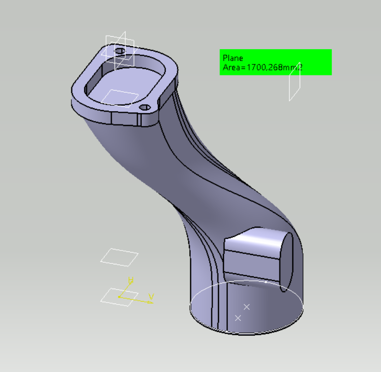
Heres something for fasteddie and me, I know you want a solution aswell to get rid of the small restriction. The market for this pipe is small though since were only two that runs this kind of IC routing
I measured som areas, and the top of the short boost pipe is around 1700mm2, and the bottom of the boost pipe is only 40m diameter (where the turbo normally connects), so 1256mm2. So the restriction in the system needs to increase to at least 1700mm2 to not be the smallest part of the boost pipe system ( equivalent to a 47mm circular pipe). So a 2inch hose would probably be a smarter choice than the 2,5 inch that naturally goes on there, for packaging reasons.
Anyway, i forgot most of what i knew in cad, so its quite a challenge to get this complex part right, it will probably take a long time to get this done. But hopefully it will be wort it with better packaging and less restriction
Heres a draft of where im at, mostly to get the different measurements right.
_________________
1980 924 Turbo
www.instagram.com/garagecedric/ |
|
| Back to top |
|
|
Fasteddie313

Joined: 29 Sep 2013
Posts: 2596
Location: MI
|
| Posted: Thu Dec 10, 2020 11:31 am Post subject: |
|
|
Ooh yes that..
| C�dric wrote: | | The market for this pipe is small though since were only two that runs this kind of IC routing |
So far..
So reduce to 2” somewhere after the intercooler and it will about equal the inlet of the upper charge tube anyway?
Would fit past the cold housing easier..
_________________
80 Turbo - Slightly Modified |
|
| Back to top |
|
|
Cedric
Joined: 27 Aug 2004
Posts: 2608
Location: Sweden
|
| Posted: Thu Dec 10, 2020 6:10 pm Post subject: |
|
|
| Fasteddie313 wrote: | Ooh yes that..
| C�dric wrote: | | The market for this pipe is small though since were only two that runs this kind of IC routing |
So far..
So reduce to 2” somewhere after the intercooler and it will about equal the inlet of the upper charge tube anyway?
Would fit past the cold housing easier.. |
A 2 inch pipe is even larger diameter than the smallest area of the upper charge tube, so I think i will evaluate that aswell to see if I can get more space down there. I will have to redo my very special squeezed tube, but it might be worth it. Maybe i will print more pipes to get more clearance with the odd shapes needed.
Its always interesting how much power you can actually push through that 40mm hole we have today, as we have seen. But it will cost you compressor capacity to keep that boost level with the restriction. So if you changed the pipe you would probably be able to get more out of your current turbo.
_________________
1980 924 Turbo
www.instagram.com/garagecedric/ |
|
| Back to top |
|
|
morghen

Joined: 21 Jan 2005
Posts: 8879
Location: Romania
|
| Posted: Thu Dec 10, 2020 7:16 pm Post subject: |
|
|
Oh Catia
This should be good!

note: when designing my tubes, i always check the internal area in different sections. Catia has a way of blending surfaces in such a way that sometimes you get less cross-section area.
| C�dric wrote: | Heres something for fasteddie and me, I know you want a solution aswell to get rid of the small restriction. The market for this pipe is small though since were only two that runs this kind of IC routing
I measured som areas, and the top of the short boost pipe is around 1700mm2, and the bottom of the boost pipe is only 40m diameter (where the turbo normally connects), so 1256mm2. So the restriction in the system needs to increase to at least 1700mm2 to not be the smallest part of the boost pipe system ( equivalent to a 47mm circular pipe). So a 2inch hose would probably be a smarter choice than the 2,5 inch that naturally goes on there, for packaging reasons.
Anyway, i forgot most of what i knew in cad, so its quite a challenge to get this complex part right, it will probably take a long time to get this done. But hopefully it will be wort it with better packaging and less restriction
Heres a draft of where im at, mostly to get the different measurements right.
|
_________________
https://www.the924.com |
|
| Back to top |
|
|
Cedric
Joined: 27 Aug 2004
Posts: 2608
Location: Sweden
|
| Posted: Thu Dec 10, 2020 7:53 pm Post subject: |
|
|
| morghen wrote: | Oh Catia
This should be good!
note: when designing my tubes, i always check the internal area in different sections. Catia has a way of blending surfaces in such a way that sometimes you get less cross-section area.
| C�dric wrote: | Heres something for fasteddie and me, I know you want a solution aswell to get rid of the small restriction. The market for this pipe is small though since were only two that runs this kind of IC routing
I measured som areas, and the top of the short boost pipe is around 1700mm2, and the bottom of the boost pipe is only 40m diameter (where the turbo normally connects), so 1256mm2. So the restriction in the system needs to increase to at least 1700mm2 to not be the smallest part of the boost pipe system ( equivalent to a 47mm circular pipe). So a 2inch hose would probably be a smarter choice than the 2,5 inch that naturally goes on there, for packaging reasons.
Anyway, i forgot most of what i knew in cad, so its quite a challenge to get this complex part right, it will probably take a long time to get this done. But hopefully it will be wort it with better packaging and less restriction
Heres a draft of where im at, mostly to get the different measurements right.
[img]https://rejsa.nu/im/user/1552/2020-12-09-23-32-38_boostpipe.pnb[/img] |
|
Yeah that function really do take some work, one reason im using catia (except for that i worked with it 10 years ago, so I still remember something) is that i have friends who work in it on a daily basis. So its much easier to get help, one of them did actually design aluminum boost pipes for trucks for many years. I think he might be able to sort this out 
_________________
1980 924 Turbo
www.instagram.com/garagecedric/ |
|
| Back to top |
|
|
Fasteddie313
Joined: 29 Sep 2013
Posts: 2596
Location: MI
|
| Posted: Thu Dec 10, 2020 9:19 pm Post subject: |
|
|
To me it’s not just the size of the 40mm hole, but that god awful 90 degree step inside of it that just can’t be good for smooth flow..
I have almost thought about replumbing/replacing the entire upper charge tube, but I quite like keeping the original upper charge tube..
Do you think replacing the lower charge tube will make for a noticeable improvement?
I think it may..
_________________
80 Turbo - Slightly Modified |
|
| Back to top |
|
|
Cedric
Joined: 27 Aug 2004
Posts: 2608
Location: Sweden
|
| Posted: Thu Dec 10, 2020 10:32 pm Post subject: |
|
|
| Fasteddie313 wrote: | To me it’s not just the size of the 40mm hole, but that god awful 90 degree step inside of it that just can’t be good for smooth flow..
I have almost thought about replumbing/replacing the entire upper charge tube, but I quite like keeping the original upper charge tube..
Do you think replacing the lower charge tube will make for a noticeable improvement?
I think it may.. |
Yes absolutely, that step is bugging me alot, its quite ironic that Ive been chasing people with the torch at work for many years to remove ugly designs and focus on pressure losses.. But now when it comes to my own personal engine i have that massive ugly restrictor in the pipe  . That ugly step will make the actual diameter that the flow can use smaller than 40mm due to the flow separation that will occur around the edge, a more smooth transition will improve that( if you for example made an insert with a nice bellmouth shape (which is my back up plan), but its still limited. . That ugly step will make the actual diameter that the flow can use smaller than 40mm due to the flow separation that will occur around the edge, a more smooth transition will improve that( if you for example made an insert with a nice bellmouth shape (which is my back up plan), but its still limited.
I could try to replicate it in my simulation model, I would expect the difference for my engine to be smaller. Since I have a larger compressor that works at a lower target boost, so more margins. The more on the limit you are with the compressor the bigger the difference will be. But you would most likely need a dyno to verify it.
Btw, check your car thread, theres some #6 housings happening !
For me the upper charge tube is essential to keep, for estethic and originality reasons.
_________________
1980 924 Turbo
www.instagram.com/garagecedric/ |
|
| Back to top |
|
|
Cedric
Joined: 27 Aug 2004
Posts: 2608
Location: Sweden
|
| Posted: Sun May 23, 2021 2:03 am Post subject: |
|
|
Just a dump of pics, i have been lazy with the updates over here. Ive not put in massive ammounts of time over winter, but its alot of small things thats been going on to get it ready for this season.
Brake cooling ducts, printed in ABS-CF, took many iteriations to get them to clear everything. they are mounted with the arb fasteing screw. I tried them in my flow bench setup and evaluated the air speeds and they seem to work decently.
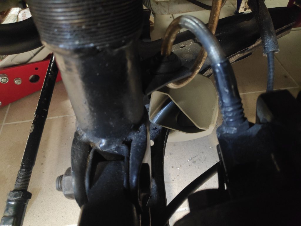
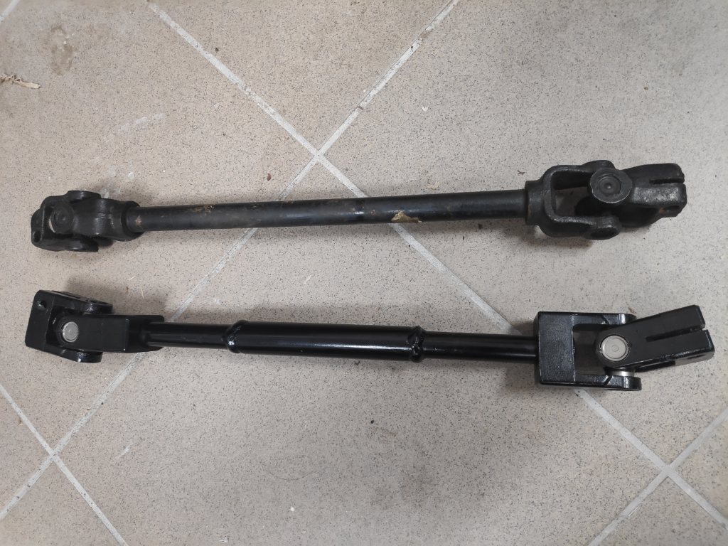
This bugger took ages and ages to fit, since it needs body mods to fit the newer shaft on the older cars, absolute shite of a job. The old one had some but minimal play, it could be heard but you cant feel it when the shaft is of the car. im picky about steering feel so it was nice with a new one.
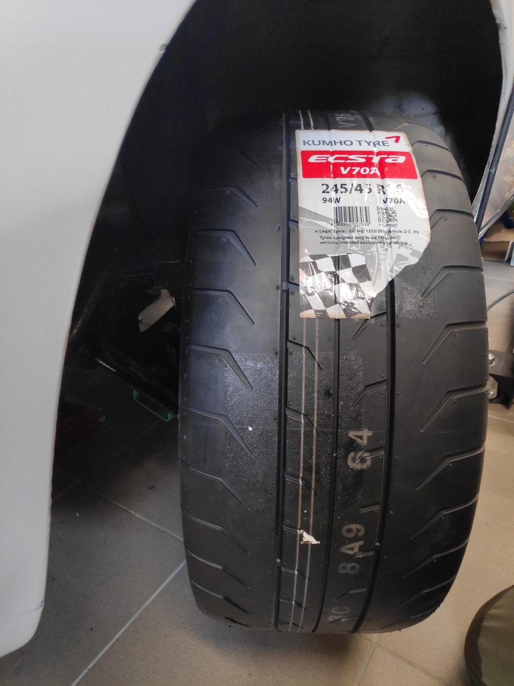
Trying my new track wheels and checking clearence, will work fine.
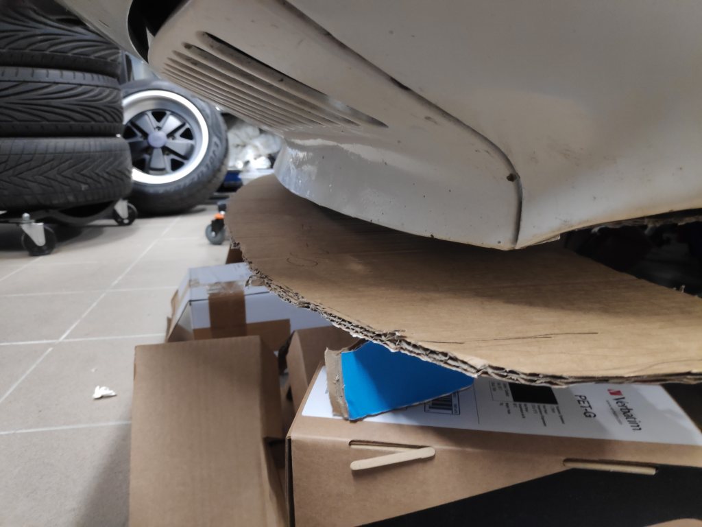
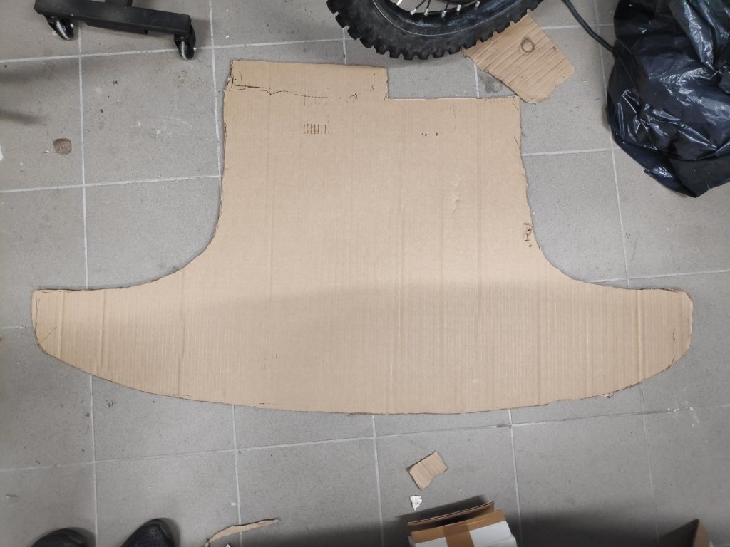
Also planining on a fron undertray, 0,69 square meters should yield a nice gain of downforce and lower drag. We will se when i finish it, it needs alot of work with the fastening, and as usual i try to use only original mounting points. I will measure the actual df levels whe its on the car.
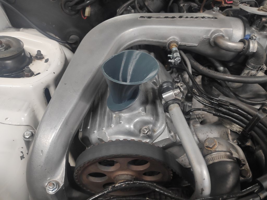
This little bugger has been very popular and sent all over the world, when i have energy enough i might print more of them, the shipping is a bit of a hassle. I got so fed up with with funnels falling out, so made a lockable one.
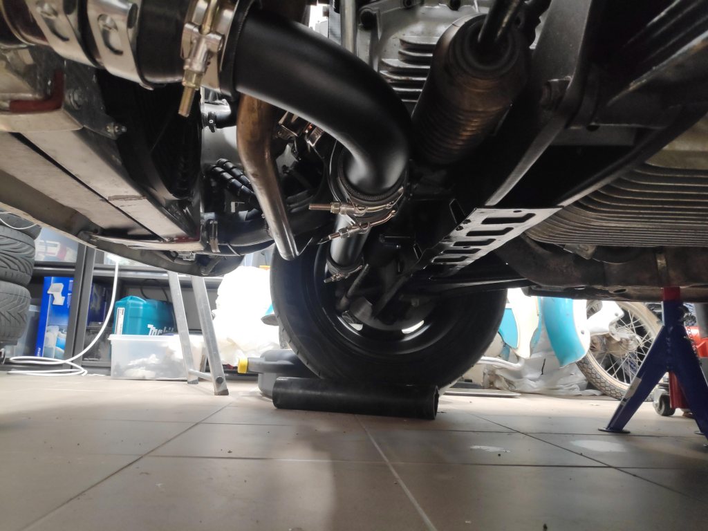
changed the boost piping from 2,5 to 2inch to get better ground clearance, its now much better and MOT ramps will no longer be an issue. and the alu pipes are black and more stealthy.
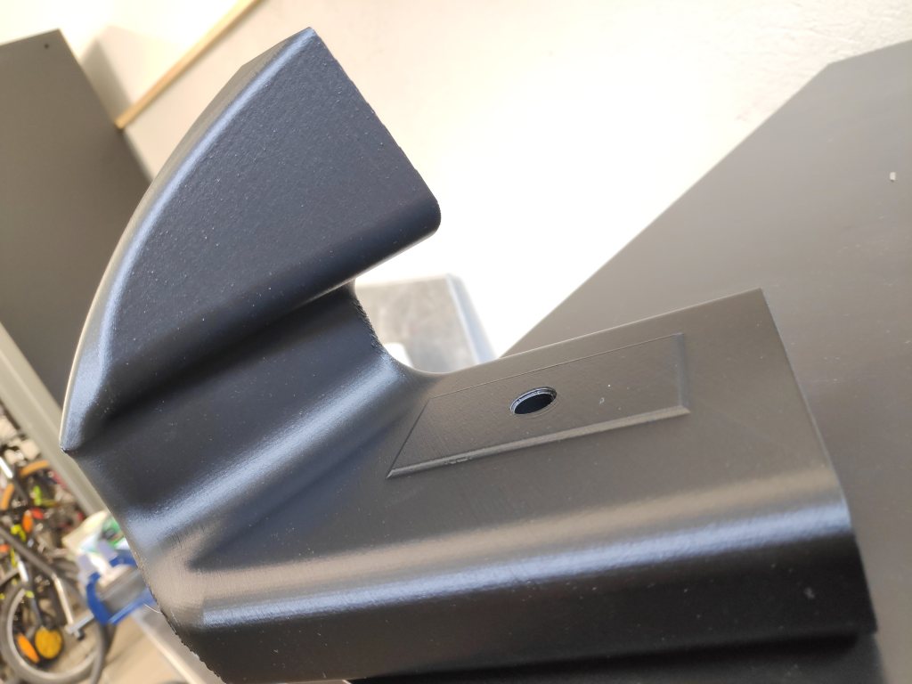
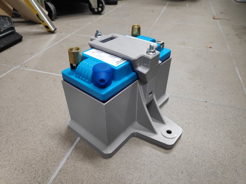
Deisgned this holder for my lightweight battery, its very sturdy and infinite amounts better than the crappy original one, and the battery is 10kg lighter
_________________
1980 924 Turbo
www.instagram.com/garagecedric/ |
|
| Back to top |
|
|
morghen
Joined: 21 Jan 2005
Posts: 8879
Location: Romania
|
| Posted: Sun May 23, 2021 5:51 am Post subject: |
|
|
Amazing stuff!
Those brake ducts look fantastic!
_________________
https://www.the924.com |
|
| Back to top |
|
|
Rasta Monsta

Joined: 12 Jul 2006
Posts: 11723
Location: PacNW
|
| Posted: Sun May 23, 2021 10:16 am Post subject: |
|
|
Looking pretty tidy man! Home manufacturing, super fun.
_________________
Toofah King Bad
- WeiBe (1987 924S 2.5t) - 931 S3
|
|
| Back to top |
|
|
Juho

Joined: 03 Oct 2018
Posts: 377
Location: Finland
|
| Posted: Sun May 23, 2021 7:51 pm Post subject: |
|
|
| Very cool! im planning to 3dprint brake cooling ducts myself too to replace the stock fog lights. |
|
| Back to top |
|
|
Cedric
Joined: 27 Aug 2004
Posts: 2608
Location: Sweden
|
| Posted: Wed May 26, 2021 7:25 pm Post subject: |
|
|
BTW, i signed for a Time Attack competition on the 28th of August, for "club" class. I will use a new rule which makes it possible for cars with 170hp or under (in the papers) to run with Rcomp tyres instead of the typical 200tw ish rules, which will offset my power disadvantage a bit hopefully . If it is like most other races it will be a quiality live stream available, which is fun. However i really need to get some testing carried out before since my car havent been on track for years, and ice changed alot, especially around the engine. Might be that i run std boost for this season on track, its alot more powerful than before anyway.
Due to demand from friends ive started an instagram account on which i will post up som pics in the future
https://www.instagram.com/garagecedric/
_________________
1980 924 Turbo
www.instagram.com/garagecedric/ |
|
| Back to top |
|
|
Mike9311

Joined: 14 Dec 2004
Posts: 1678
Location: Chicago-ish
|
| Posted: Thu May 27, 2021 2:40 am Post subject: |
|
|
Love all of this Cedric
All of this stuff is revolutionizing how we take care and modify our cars.... Awesome
20 years ago I would not have seen this future
_________________
1980 931 since 1989
1981 Ideola 931 Club Sport
1982 931 Entwicklungsfahrzeug
1979 924 NA ohne 650 mit 471
1982 931 Red Resurrection - 951 IC
1982 931 parts car / resurrection?
1980 924 NA (R&D lightweight)
1982 931 wana-be GTR race car |
|
| Back to top |
|
|
Rasta Monsta
Joined: 12 Jul 2006
Posts: 11723
Location: PacNW
|
| Posted: Thu May 27, 2021 4:15 am Post subject: |
|
|
I just saw an article where they are 3D printing homes from concrete, and touting it as a potential solution to housing shortages.
_________________
Toofah King Bad
- WeiBe (1987 924S 2.5t) - 931 S3
|
|
| Back to top |
|
|
|
|
You cannot post new topics in this forum
You cannot reply to topics in this forum
You cannot edit your posts in this forum
You cannot delete your posts in this forum
You cannot vote in polls in this forum
|
Powered by phpBB © 2001, 2005 phpBB Group
|

