 |
924Board.org
Discussion Forum of 924.org
|
| View previous topic :: View next topic |
| Author |
Message |
RC

Joined: 25 Mar 2007
Posts: 2636
Location: Australia
|
 Posted: Tue Feb 26, 2013 2:32 am Post subject: Posted: Tue Feb 26, 2013 2:32 am Post subject: |
 |
|
Nice job Jasper.
ITB = independent throttle bodies. Det cans = DIY stethoscope. Bit of hose held to engine, other end inserted into a tin can, bottle neck with open end, etc. Difficult to use while driving though and you won`t get into loaded cells in the driveway.
Hard to tune without knock sensor/ amplifier and a wideband oxygen sensor readout. Really suggest getting it tuned on a dyno once its all ready, they should have the right equipment. Tune mid & high load (boosted) cells. Find someone familiar with MSD or just hire the dyno & operator while you adjust the laptop, once you have good idea.
Don`t worry about idle advance, very safe, no load. Get smoothest & fastest idle with lowest MAP (indicates best efficiency) then reduce RPM at throttle bypass screw. I`m running 20 * as are other EFI guys, some even more @ <100KPa. Will give faster tip in from idle or part throttle, bit faster spool up. Only slightly higher NOx emissions but lower in HC & CO.
Did you use some temperature dependent retard via the additional blue wires?
_________________
World`s quickest 924 2L slushbox
| Allan @ DTA wrote: | | I have no issue with superchargers, they are for guys who want to drive a car rather than talk about horsepower with their baseball cap on backwards |
|
|
| Back to top |
|
 |
jaspervanweerd
Joined: 03 Dec 2012
Posts: 22
Location: Netherlands
|
| Posted: Tue Feb 26, 2013 7:05 am Post subject: |
|
|
| RC wrote: | Nice job Jasper.
ITB = independent throttle bodies. Det cans = DIY stethoscope. Bit of hose held to engine, other end inserted into a tin can, bottle neck with open end, etc. Difficult to use while driving though and you won`t get into loaded cells in the driveway.
Hard to tune without knock sensor/ amplifier and a wideband oxygen sensor readout. Really suggest getting it tuned on a dyno once its all ready, they should have the right equipment. Tune mid & high load (boosted) cells. Find someone familiar with MSD or just hire the dyno & operator while you adjust the laptop, once you have good idea.
Don`t worry about idle advance, very safe, no load. Get smoothest & fastest idle with lowest MAP (indicates best efficiency) then reduce RPM at throttle bypass screw. I`m running 20 * as are other EFI guys, some even more @ <100KPa. Will give faster tip in from idle or part throttle, bit faster spool up. Only slightly higher NOx emissions but lower in HC & CO.
Did you use some temperature dependent retard via the additional blue wires? |
Hi Roger,
How are you doing? As you can see its up and running using the dizzy form down under:D, how about your car car? Already returned from the paint shop?
Ok, so 18* at idle should not be such a big problem, but can I still use the standard CO adjustment method (Haynes) at idle even though its at 18* instead of 9*?
No I did not include a temp retard yet, I believe with this unit its the pink wire. So if 12v is applied on that wire one can set a certain step retard to occur. I will look into this as well
.
However, the spark MAP I made was based on the DITC one with full AIT correction applied. My aim is to compile the most conservative spark map to run the car. Also for other people interested in converting their DITC 931s or even S1s.
But you are right, the make full use of the MSD unit a dyno is a must. First a re-spray is in order  . .
Whats your opinion on the spark map? So far I do not notice any audible knock
.
Jasper |
|
| Back to top |
|
|
RC
Joined: 25 Mar 2007
Posts: 2636
Location: Australia
|
| Posted: Thu Feb 28, 2013 12:59 am Post subject: |
|
|
Hey Jasper, I`m doing well thanks, better than the previous few weeks. Car is still at the painters, just waiting a bit longer to fully cure before reassembling and buffing. Happy to wait for a quality job though.
Am pleased to see it going together well and sharing your experience here. Perhaps some others may now take the plunge and do similar. TBH, MSD isn`t my favourite ignition but does offer both the reliability, flexibility and better overall value compared to the obsolete DTIC.
18* or even up to 25* @ idle will be fine, as should CO emission. Difference is negligible really and should still be under spec I`m sure. Recall a graph on MS or tuning site that indicated variations of various pollutants, and IIRC the only drawback to advanced idle advance was increased nitrous oxide. Not even an issue unless you need to get car fully smogged.
Temp retard would be desirable to allow slightly more safe advance. Couldn`t remember what colour wire, was there not 2 inputs that can be configured? Not sure if original (DTIC) uses just a switch or a variable sensor, but a basic, yet fast responding switch at say 60 - 70* would be ideal to knock off a few degrees timing.
Your spark map appears OK but would personally bring in advance a bit slower through the midrange, not at 2.6K like you have but at 3.6 (around max TQ) or bit higher say 4 or so. In the conservative map of mine I emailed you see its @ 4.2K. Below atmo is pretty safe though, can push it a bit without damage. Its in the higher boosted range where detonation occurs. Suggest you only use other maps as a guideline, mine included. It is deliberately conservative as the engine is not fully run in but has flat top pistons with extensive mods to head/ chambers. May post the map after its set up on a dyno & pushed more. Remember all engines will be different even those with the same specs. Raceboy is running a turboed NA (9.3:1 CR if stock) as was I with the old engine. Flosho`s table looks good for a US (bit lower CR) 931, probably a better guide really. It is a dangerous and lazy exercise to merely copy something that probably was established by some trial & not much error rather than on a dyno.
Some detonation is not audible, especially in these noisy engines. Don`t rely on hearing it at low levels. I have trouble even with attached knock sensor & sophisticated filtering. Pull your plugs regularly & examine especially #3 & #4, they run hottest. Your fuel mixtures are in all honesty, anyone`s guess using CIS. Hopefully it is close to a good stock reading but without monitoring you can`t be sure. Any good dyno will have & use O2 /exhaust gas analysis and knock monitoring.
Sorry to keep pushing the point, just wouldn`t like to see you kill your engine. Also confirm that the software figures really do correspond with actual measurements at the flywheel. Not just at idle, try setting to 30 or better 40* in software at say 2 -4K @ < 70KPa (low MAP). Use dividers to space out same distance 0-10* (about 24mm IIRC) and mark flywheel accordingly. Then do reality check with timing light.
Perhaps enjoy driving it for a while on a safe tune before it goes into the paint shop. Oh, and beware of Asian drivers reversing.
Cheers
_________________
World`s quickest 924 2L slushbox
| Allan @ DTA wrote: | | I have no issue with superchargers, they are for guys who want to drive a car rather than talk about horsepower with their baseball cap on backwards |
|
|
| Back to top |
|
|
jaspervanweerd
Joined: 03 Dec 2012
Posts: 22
Location: Netherlands
|
| Posted: Sun Mar 03, 2013 1:13 am Post subject: |
|
|
That for the suggestions, I tuned the map so its a bit more conservative. Also, my DIY FPR/switch set-up is quite handy if one wants to set the initial AFR. Now its running like a charm, a bit on the rich side though. Perhaps I will acquire the MSD tach/fuel adapter, but for now this set-up gives me quite some freedom (BTW no more hot start issues since I can purge the fuel system manually if I so desire, WOT trick also works fine ideola )
Also, I confirmed that the MSD unit is retarding the ignition like it should...
Quite pleased with how this project turned out. Next things on my To-Do list:
- Make a how-to of course
- Replace the oil (any suggestions?), filter and such
- Give the brakes a once over
- Paint the whole car, friendly painter of mine does the job for 500 euro's excluding the roof since its still in good condition
- Mount rear spacer, now it looks a bit goofy
- And.....drum rolll....visit the dyno guys to get it dialed in nicely.
I want to thanks all the people that commented on this topic.
Coming back to questions that were raised earlier, ignition accuracy. A trigger wheel will be much better and yield a stable signal. However, for my application that amount of accuracy is not required. But MSD has very nice kits that do the trick nicely. I chose to use Roger (RC) dizzy since it is a complete working package. Most likely one can retrofit the S2 dizzy with a pick-up system as well.
PS. Does somebody have bolt-on 20 mm spacers for sale, my wheel studs are too short for the stock Porsche ones (I have two of those lying around).
One flywheel sensor, S2 dizzy, RoW EURO DITC box and ignition module still for sale !!! |
|
| Back to top |
|
|
morghen

Joined: 21 Jan 2005
Posts: 8884
Location: Romania
|
| Posted: Sun Mar 03, 2013 4:42 am Post subject: |
|
|
For the 924 turbo, i use MOTUL 300V Competition.
_________________
https://www.the924.com |
|
| Back to top |
|
|
RC
Joined: 25 Mar 2007
Posts: 2636
Location: Australia
|
| Posted: Mon Mar 04, 2013 9:00 pm Post subject: |
|
|
Bolt on wheel spacers are intrinsically unsafe. They`re banned in Australia for that reason. Perhaps check with your local vehicle authority.
The stock type (22mm IIRC) spacers are best option along with a change of studs. Pretty easy to remove the rear hubs, 36mm socket / spanner & big leverage. Studs are easy to press or hammer out and simply replace with longer ones. OE studs come in a few lengths and are not overly expensive, about $9 ea. Did the same swap and got a S/H set from Ideola I think. Perhaps post a WTB. Even shipping from US via USPS is only ~$17.
Paint job and a dyno tune sounds like money well spent. There is a lot more power to be gained safely by optimal tuning of the advance curve. Sure it will give a big  . Drive & enjoy. . Drive & enjoy.
_________________
World`s quickest 924 2L slushbox
| Allan @ DTA wrote: | | I have no issue with superchargers, they are for guys who want to drive a car rather than talk about horsepower with their baseball cap on backwards |
|
|
| Back to top |
|
|
Raceboy

Joined: 01 Mar 2004
Posts: 2326
Location: Estonia, Europe
|
| Posted: Mon Mar 04, 2013 9:33 pm Post subject: |
|
|
Porsche selles bolt on spacers and in the same manner, the 5lug 944/931/924S wheel hub is also a bolt-on wheel spacer (having studs in the aluminium).
When made of proper grade aluminium with correct tolerances, it is very safe. Of course some guys cannot even torque 20 lug nuts properly, they obviously would make more mistakes with 30 or 40 Not referring to anyone specifically as a sidenote.
_________________
'83 924 2.6 16v Turbo, 470hp
'67 911 2.4S hotrod
'90 944 S2 Cabriolet
'78 924 Carrera GT replica
'84 928 S, sold
'91 944 S2, sold
'82 924S/931 "Gulf", sold 
'84 924, turbocharged, sold.
http://www.facebook.com/vemsporsche |
|
| Back to top |
|
|
McGyver

Joined: 24 Feb 2009
Posts: 354
Location: Jelenia Gora - Poland
|
| Posted: Wed Apr 03, 2013 3:49 am Post subject: |
|
|
Do you think that Electronic Ignition will work better than DITC? Assuming repair problems with DITC I think only problem is that @#@#$ Stupid Flywheel sensor which could be replaced with something more modern somehow - I still don;t have enough time to complete understand how DITC really works. Flywheel sensor looks like two connected coils in one "box" - but someone had to cut one bad unit to find it out... is there someone which got damaged sensor?
DITC is quite easy to repair this times and parts for it are quite cheap.
That's truth you can't modify it too much for modern fuels for example, so that's modern EI will work much better, especially if you can add some more sensors to it... like knock sensor  which should help to save engine for much longer than DITC. which should help to save engine for much longer than DITC.
Really great tutorial But add some info abut that locked distributor - it should be easy to convert from S2 original distributor... and S1 should be locked (in which position? or any but it should be set after that in specific direction?).
_________________
931 82' - 5000km after full engine rebuild
SOLD: 924 81' N/A- with turbo gearbox "dogleg" - great but mysterious car
www.mauser98k.internetdsl.pl - if someone like german rifles (English version avalible) |
|
| Back to top |
|
|
jaspervanweerd
Joined: 03 Dec 2012
Posts: 22
Location: Netherlands
|
| Posted: Sun Apr 06, 2014 9:51 pm Post subject: |
|
|
It has been a while now, so lets give an update after more or less a year of driving around with the MSD unit. So far, it hasn't let me down and I can really recommend the conversion !!!
In my case I used a locked-out dizzy that was already prepped for use. Of course a flywheel pick-up would be much more accurate. But if you are not pushing the limit it wouldn't worry to much about that. I am not sure if you can easily retrofit the s2 dizzy with a pick-up sensor though. I wouldn't go as far in claiming it outperforms the stock DITC, but it does give you a bit more freedom and less components to fail like the ignition amplifier, temp sensor, flywheel and TPS sensor and so forth.
During the last year I did make some adjustments to the ignition map, see below:

Car runs really nice with this map. As you can see max advance is 30*, no vacuum advance only boost retard (still a bit conservative). Keep in mind though, I always use the best quality fuel in the Netherlands (RON98) to prevent detonation from occurring. The conservative boost map, due to the lack of a temp. retard and intercooler, will complement this.
In addition during cranking the ignition timing is set at 5* BTDC to help in both hot and cold starting. The idle is set at ~ 950 rpm at a CO level of ~ 1.5%.
HEADS_UP !!!
I did notice that the deceleration valve isn't working properly in this configuration. The stock system detects when the throttle is closed and adjusts the timing accordingly. However, when I was playing around with the vacuum advance I had to richen to mixture quite a lot to get the rpm to drop between shifts. I checked the valve but it seems to function like it should. So in my car the deceleration valve vacuum line is not hooked up to the intake manifold. I have no problems when lifting the throttle, no banging exhaust and such.
So for people wanting to try this conversion, the spark map given in the picture works pretty good, for a EURO 931 that is. Also keep in mind I dialed in everything after giving the car a big ass service e.g. cylinder head refurbishment, exhaust manifold repair (yes, yes cracks), oil, coolant, filters, thermostat, cam belt, water pump, spark plug, HT leads etc etc
Meaning, everything was in good working order. I cannot guarantee, but I would expect, that it works well with the above, final map. |
|
| Back to top |
|
|
ideola

Joined: 01 Oct 2004
Posts: 15548
Location: Spring Lake MI
|
| Posted: Sun Apr 06, 2014 10:34 pm Post subject: |
|
|
Jasper, this is fantastic stuff. Thanks very much for doing the legwork and posting the results!
_________________
erstwhile owner of just about every 924 variant ever made |
|
| Back to top |
|
|
techfx
Joined: 11 Feb 2014
Posts: 25
Location: Pittsburgh, PA
|
| Posted: Thu May 08, 2014 6:04 am Post subject: |
|
|
| I would like to try this if I ever get all of my other bugs worked out (although this may fix a few). Nice write up! |
|
| Back to top |
|
|
jaspervanweerd
Joined: 03 Dec 2012
Posts: 22
Location: Netherlands
|
| Posted: Sat May 10, 2014 6:23 am Post subject: |
|
|
small update !!!
The PO, for some reason thought it was wise to use some ducting often found in ponds and such to replace the bellows between the fuel dizzy and the turbo. This was giving a vacuum leak since it wasn't sealing properly. The old bellows, which I found in the 'parts bin' that came with the car, had a crack.
Since this part is NLA, I found a replacement that suits well:
http://www.autosportcompany.nl/silicone-bellow-4631.html#.U202-nSKAdU
Its has the same inner diameter (60 mm) and is made out of silicone rubber reinforced with steel rings that prevent inflation and deflation of the tube (it doesn't deform at all !!!)
So after installing this, setting the CO etc etc the vacuum limiter/deceleration valve worked !!!
Also idle is much better and so forth.
In addition, I always had a rattle/grinding noise coming from the passenger footwell when the engine was under load or the car was decelerating. The noise seemed drivetrain related since pressing the clutch caused the noise to disappear. Knocking was excluded since changing the timing, very handy with the MSD, didn't affect this. After looking underneath the car I noticed there was only one bolt holding on the wastegate with the torque tube bracket. Gaining access to this mount is quite tricky but doable. What I did was remove the starter and you basically can access every nut and bolt, though a bit fiddly. Added another nut and bolt tightened everything and viola the rattle is gone !!! |
|
| Back to top |
|
|
mrgtturbo

Joined: 06 Jan 2003
Posts: 526
Location: Skowhegan, ME
|
| Posted: Wed Mar 11, 2015 6:28 am Post subject: |
|
|
I wish to do this conversion but I'm running into dead ends. Could someone please tell me what pick up sensor I'm supposed to purchase? Everyone is telling me there isn't one available for my car.
81 931
Thanks.
Aaron
_________________
81' 931 |
|
| Back to top |
|
|
ideola
Joined: 01 Oct 2004
Posts: 15548
Location: Spring Lake MI
|
| Posted: Wed Mar 11, 2015 11:04 pm Post subject: Re: TUTORIAL alternative to the DITC ignition, MSD 6530 |
|
|
| jaspervanweerd wrote: |
Step 3: The distributor
Next we need to swap out the DITC dizzy for the locked-out one that has a pickup sensor. First I soldered a connector, included in the MSD package, to the dizzy magnetic pickup sensor connector on the dizzy body, see picture.
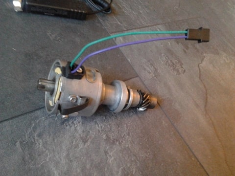
This connector would hook up to directly to the wiring loam coming out of the bulkhead. Since I cut of the connector of this wire so I could feed it through the bulkhead, I re-soldered it on and protected/insulated it with electrical tape. |
Can we get more information on the pickup sensor?
Also, I am not clear if it works like a crank reference, where it picks up ONE signal from a magnet on the rotating portion of the distributor, or if it picks up EACH of the four arms as they rotate past the sensor.
_________________
erstwhile owner of just about every 924 variant ever made |
|
| Back to top |
|
|
RC
Joined: 25 Mar 2007
Posts: 2636
Location: Australia
|
| Posted: Sun Mar 15, 2015 11:12 pm Post subject: |
|
|
The pickup is a standard 4 pole variable reluctor, as fitted to 931 S1 models and most NAs, on Euro & ROW anyway and most US models too I believe. It is just a simple coil of wire mounted to a 4 prong stator incorporating a magnet and triggered by the 4 prong rotor fitted to the distributor shaft. This generates a sine wave crossing the 0 point, 4 times per dizzy revolution, 720* @ crank. Amplitude will vary depending on RPM as does the frequency. Therefore there is one signal corresponding to every plug firing, like 4 per 720* cycle, same as a stock distributor.
Any 924 distributor can be utilized here, as long as it fits and is the reluctor type. Check the shaft & bushes for any play or rebuild if necessary to prevent any timing scatter. The mechanical and vacuum advance curves are irrelevant, as the mechanisms need to be removed and the shaft locked together as one. Some butchers wire, or worse weld, the shafts together, which usually result in dwell & timing variations. The simplest correct procedure involves fabricating a plate to fit between and connect the upper & lower shafts, screwing through the obsolete weight holes. Should be clearer upon dismantling.
Ideally the shafts & pickup plate should be aligned so that the reluctor prongs align at 45-50* BTDC while the rotor is pointing to the cap contact at ~25* BTDC, average assuming 10* idle minimum and 40* max advance.
_________________
World`s quickest 924 2L slushbox
| Allan @ DTA wrote: | | I have no issue with superchargers, they are for guys who want to drive a car rather than talk about horsepower with their baseball cap on backwards |
|
|
| Back to top |
|
|
|
|
You cannot post new topics in this forum
You cannot reply to topics in this forum
You cannot edit your posts in this forum
You cannot delete your posts in this forum
You cannot vote in polls in this forum
|
Powered by phpBB © 2001, 2005 phpBB Group
|

