 |
924Board.org
Discussion Forum of 924.org
|
| View previous topic :: View next topic |
| Author |
Message |
Rich H
Joined: 10 Jun 2007
Posts: 2665
Location: Preston, Lancs, UK
|
 Posted: Thu Feb 19, 2009 1:11 am Post subject: Posted: Thu Feb 19, 2009 1:11 am Post subject: |
 |
|
PVC melts at a prety low temp, acrylic might be better but it shatters.
I like the idea of a sliding fit metal runner, use screw jacks to drive it in and out.
Or a variation on the rotary valve type with a continuously variable length. I have an idea but I need to draw it out and take a pic (I'm useless at computer drawings it takes me ages  ) )
Basically its a U pipe but the inside edge is formed around a central spindle. The air comes in to the center and is directed out by a spiral piece the edge of the spiral runs inside of outside of the U and can be moved around. That sounds dreadful but a couple of sketches might make some more sense I'll draw it all later.
_________________
1994 Lotus Esprit S4 - Work in progress...
1980 Porsche 924 S2 DITC Turbo - Original spec
1978 Homo-Sapiens - Tired spec
1953 Landrover S1 - Pensioner Spec |
|
| Back to top |
|
 |
ideola

Joined: 01 Oct 2004
Posts: 15548
Location: Spring Lake MI
|
| Posted: Thu Feb 19, 2009 1:24 am Post subject: |
|
|
Yeah, I did some quick searching on a variety of thermo-plastics, and it seems the best ones are only rated up to 200°F. I'd also be worried about the cement bonding letting go due to NVH.
Still, with CPVC (rated at 200°), it might be possible to cheaply construct a prototype that would be durable enough to test and perfect on the dyno. If the design showed measurable benefits, once perfected, it could then be constructed out of alu stock.
Rich, definitely interested in your spiral concept...please post pix or send 'em to me via email, and maybe I can do 'em up electronically...
_________________
erstwhile owner of just about every 924 variant ever made |
|
| Back to top |
|
|
Rich H
Joined: 10 Jun 2007
Posts: 2665
Location: Preston, Lancs, UK
|
| Posted: Thu Feb 19, 2009 2:35 am Post subject: |
|
|
OK wanky pic but you should get the idea:
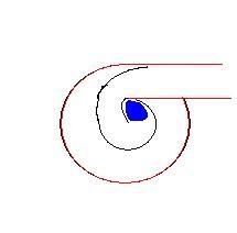
Red section is the casing made from a P shaped pipe with the inside cut away (Square section makes things easier to form and seal?) black is the movable bit, blue blob is the air inlet, engine is off to the right. Problem is the inlet as it's in the center and rotates off centre but it's not that difficult to fix. You can get around 180* of rotation before it binds adn that will add probably 50% to the intake runner length. If you use a larger diameter for the case you can get a much longer increase. The seal of the spiral bit is mostly irrelevant as the other end of the case is a dead end so there is no pressure differential to deal with.
Make up 4 and gang them together, make the central section out of a single piece of pipe and use it as a plenum, bung a throttle on the end...
does that make any sense at all?
_________________
1994 Lotus Esprit S4 - Work in progress...
1980 Porsche 924 S2 DITC Turbo - Original spec
1978 Homo-Sapiens - Tired spec
1953 Landrover S1 - Pensioner Spec |
|
| Back to top |
|
|
Rich H
Joined: 10 Jun 2007
Posts: 2665
Location: Preston, Lancs, UK
|
| Posted: Thu Feb 19, 2009 2:45 am Post subject: |
|
|
Thinking about it, at its simplest, have your P shaped pipe with the insides missing
Inside that put a pipe with a slot along its length that can rotate.
Rotate the pipe the air path gets longer, the air wont back up into the dead space as there is nowhere for it to go (OK its not exactly the most efficient way but itll do) You could even put a bit of intake air into the back of the chamber to prevent any backflow.
Put your throttle body onto the central pipe with a sliding coupling and a mech to rotate the pipe. You then have a variable inlet length in a fairly crude but functional sort of way.
Either bend up pipe and cut it or make up flat sheets and tack strips into the P shape. The pipe can just be cut to suit.
_________________
1994 Lotus Esprit S4 - Work in progress...
1980 Porsche 924 S2 DITC Turbo - Original spec
1978 Homo-Sapiens - Tired spec
1953 Landrover S1 - Pensioner Spec |
|
| Back to top |
|
|
ideola
Joined: 01 Oct 2004
Posts: 15548
Location: Spring Lake MI
|
| Posted: Thu Feb 19, 2009 4:07 am Post subject: |
|
|
I get it, totally, let me work this up with some real world dimensions. According to one source I was reading, the variable length doesn't have to be individualized to four runners, you can actually have the airflow path lengthened with in the plenum itself, which is precisely how the BMW interlocking scrolls work. So I think this could be accomplished pretty easily, and would even allow of the addition of velocity stacks in the primary plenum to aid the airflow going into the runners.
As I said, let me play with some real dimensions...the cool thing is that I can sort out the rotational aspects in the computer to make relatively certain that the geometry will work without binding up on anything. The toughest part will be fabricating the scroll, but as you suggest, it doesn't have to be circular, it could be put together with sheets. Cool idea!
_________________
erstwhile owner of just about every 924 variant ever made |
|
| Back to top |
|
|
Rich H
Joined: 10 Jun 2007
Posts: 2665
Location: Preston, Lancs, UK
|
| Posted: Thu Feb 19, 2009 4:21 am Post subject: |
|
|
If the end of the spiral in the center is enlarged to a cylinder it will reduce the sharp edge i there.
I look forward to the results.
_________________
1994 Lotus Esprit S4 - Work in progress...
1980 Porsche 924 S2 DITC Turbo - Original spec
1978 Homo-Sapiens - Tired spec
1953 Landrover S1 - Pensioner Spec |
|
| Back to top |
|
|
ideola
Joined: 01 Oct 2004
Posts: 15548
Location: Spring Lake MI
|
| Posted: Thu Feb 19, 2009 4:38 am Post subject: |
|
|
One challenge that immediately comes to mind is that you don't want the inlet into the spiral to be too small because it will then become a restriction. I am going to come up with a design based on ITBs, so there will be no upstream TB before the spiral. However, I suspect that the entry into the spiral is going to need to be about 60mm diameter at minimum, which is the stock 931 SII TB diameter.
What this means is that the resulting plenum is going to be a bit larger than 100m diameter in order to be able to fit a scroll that will wrap around enough to create additional length. However, with this design, there is no need for a diffuser plenum or a primary plenum...the scroll-plenum will serve the purpose of plenum and runner simultaneously, so the volume can be much greater than with a conventional plenum. Fun, fun!
_________________
erstwhile owner of just about every 924 variant ever made |
|
| Back to top |
|
|
Rich H
Joined: 10 Jun 2007
Posts: 2665
Location: Preston, Lancs, UK
|
| Posted: Thu Feb 19, 2009 4:49 am Post subject: |
|
|
100mm isn't very big, I was thinking twice that O/D...
_________________
1994 Lotus Esprit S4 - Work in progress...
1980 Porsche 924 S2 DITC Turbo - Original spec
1978 Homo-Sapiens - Tired spec
1953 Landrover S1 - Pensioner Spec |
|
| Back to top |
|
|
ideola
Joined: 01 Oct 2004
Posts: 15548
Location: Spring Lake MI
|
| Posted: Thu Feb 19, 2009 4:52 am Post subject: |
|
|
| Rich H wrote: | | 100mm isn't very big, I was thinking twice that O/D... |
Yeah...the previous designs were all based on similar dimensions of the stock plenum. I did some basic calcs, and the stock plenum is about 92-95mm in diamter (NA/931 respectively), and comes out to just under 2L of volume. I was trying to stay close to those numbers. In the case of a scroll plenum, I think it's not such a big deal...working on it now.
_________________
erstwhile owner of just about every 924 variant ever made |
|
| Back to top |
|
|
ideola
Joined: 01 Oct 2004
Posts: 15548
Location: Spring Lake MI
|
| Posted: Thu Feb 19, 2009 6:50 am Post subject: |
|
|
OK, no time for commentary at the moment, but here are the designs. VERY promising!

_________________
erstwhile owner of just about every 924 variant ever made |
|
| Back to top |
|
|
Rich H
Joined: 10 Jun 2007
Posts: 2665
Location: Preston, Lancs, UK
|
| Posted: Thu Feb 19, 2009 7:00 am Post subject: |
|
|
Looking good. Wouldn't want to have build it though! 
Make it a drum shape, seal the bellmouths into a backing plate to fill the hole. Central air feed (Both ends?) I think the bit that needs work is the transition from central tube to swpet area, the sharp edge needs to be rounded out more to reduce that short turn.
_________________
1994 Lotus Esprit S4 - Work in progress...
1980 Porsche 924 S2 DITC Turbo - Original spec
1978 Homo-Sapiens - Tired spec
1953 Landrover S1 - Pensioner Spec |
|
| Back to top |
|
|
ideola
Joined: 01 Oct 2004
Posts: 15548
Location: Spring Lake MI
|
| Posted: Thu Feb 19, 2009 8:11 am Post subject: |
|
|
Yeah, thinking about it on the way home, the "baffle" that is depicted as three straight pieces could just as easily be a section cut from a radiased tube. I'll update the drawing to reflect that, which should help with the transition.
As for the central tube itself, I didn't indicate it on the drawing, but what I would do is make that into a cone-shaped diffuser, which will evenly distribute the incoming air across a rectangular interface port, just like what's on my current custom manifold design. The diffuser approach is a proven way to evenly distribute air across a rectangular slot when forcing air to make a 90° turn. This approach will allow for a simple construction of the central tube, and allow for inlet air to be a direct path from a cold air intake, direct from a turbo outlet, s/c outlet, or a front mount intercooler.
I'll play with a drum shape, but you need the runners to come at an angle as depicted in order to keep the IM within the same volume of space as the original manifold. If you angle the drum, you'll end up losing radius on the back side (long path/low rpm position) of the baffle's travel, which will reduce the total length and amount of variable travel.
The trickiest part I see with this design is getting a good positive seal where the inner cylinder+baffle assembly needs to rotate, which will obviously be absolutely vital. I'm already thinking of a simple vacuum actuated push rod configuration adapted from the Volvo design posted earlier to control rotation of the baffle. Of course, some type of motor could also be used tied to a PWM output on ECU-equipped cars.
_________________
erstwhile owner of just about every 924 variant ever made |
|
| Back to top |
|
|
Rich H
Joined: 10 Jun 2007
Posts: 2665
Location: Preston, Lancs, UK
|
| Posted: Thu Feb 19, 2009 8:25 am Post subject: |
|
|
Some sort of sealed bearing would sort the ends, the most important seal would then be the one on the edge of the bell mouth plate to stop the air shortcutting, but a good close fit would do, once the air is moving it won't be much of an issue.
_________________
1994 Lotus Esprit S4 - Work in progress...
1980 Porsche 924 S2 DITC Turbo - Original spec
1978 Homo-Sapiens - Tired spec
1953 Landrover S1 - Pensioner Spec |
|
| Back to top |
|
|
ideola
Joined: 01 Oct 2004
Posts: 15548
Location: Spring Lake MI
|
| Posted: Thu Feb 19, 2009 8:31 am Post subject: |
|
|
| Rich H wrote: | | a good close fit would do, once the air is moving it won't be much of an issue. |
Yeah, that's what I was thinking too.
_________________
erstwhile owner of just about every 924 variant ever made |
|
| Back to top |
|
|
ideola
Joined: 01 Oct 2004
Posts: 15548
Location: Spring Lake MI
|
| Posted: Thu Feb 19, 2009 2:17 pm Post subject: |
|
|
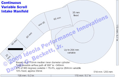
OK, round two on the scroll-style continuously variable IM. (Note: the funky black shape in the center of the diagram is supposed to represent a rectangular interface port cut into a conical diffuser plenum).
Maximum runner length of ~518mm for low RPM:

Minimum runner length of ~250mm for high RPM:

First change was to use a radiused baffle for smoother airflow. Then I started playing around with the angle of the runners. Because this design allows for the use of velocity stacks, it is less important to have runners that reduce from 50mm diameter to 40mm diameter as depicted in the previous designs. I did some research on calculating runner area, and by all accounts, the stock design of ~50mm flared openings in the plenum and ~40mm at the head seems to be right on target. So I'm using those figures for all of these designs.
In any event, by going with a smaller 40mm diameter tube, it opens up a lot more flexibility for placement and angle. This latest design allows a direct straight run, no bends, right from the plenum into the ITBs and subsequently into the head. This is also accomplished in an area that is almost identical to -- in fact, just a bit smaller than -- the stock manifold.
Now, the other thing that's cool about using these smaller diameter runners is that I was able to optimize the position of them within the primary plenum, and in so doing gain another ~10° of rotation on the scroll. This allows for a maximum of ~268mm of variability. The fixed portion of the airpath is ~250mm long, so the range of variability with this design is ~250 mm to ~518 mm.
In terms of optimizing the design and operation, one of the sources I identified for calculating runner length used the basic formula of 178mm for 10,000 RPM + an addition 43 mm for every 1,000 RPM below 10,000 that you want to target your peak HP and torque. Using that math, we get the following results:
Peak HP target of 6000 RPM = 178mm + (4 * 43mm) = 350mm
Peak Torque target of 3000 RPM = 178 + (7 * 43mm) = 480mm
Approx position of baffle for optimized (480mm) low RPM configuration:
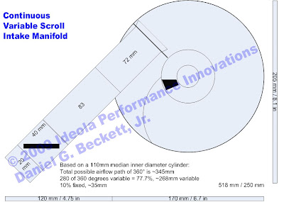
Approx position of baffle for optimized (350mm) high RPM configuration:
Now, these numbers are "close enough" guesses. There are a bunch of different methods and theories for calculating runner lengths, some using Helmholtz resonance, some not, and none of them return the same results based on the characteristics of our motor. So without lab testing, it's just a SWAG no matter how you look at it. But using the above formula gives some very attainable numbers, especially with this scroll design. On top of that, the scroll design allows for additional tweaking and tuning once on the dyno because of the fairly significant range of variability, and of course, the fact that the variable length can be attained with gradations across an RPM range, rather than a Boolean proposition like the previous two designs.
_________________
erstwhile owner of just about every 924 variant ever made |
|
| Back to top |
|
|
|
|
You cannot post new topics in this forum
You cannot reply to topics in this forum
You cannot edit your posts in this forum
You cannot delete your posts in this forum
You cannot vote in polls in this forum
|
Powered by phpBB © 2001, 2005 phpBB Group
|

