| View previous topic :: View next topic |
| Author |
Message |
Arvidw

Joined: 20 Sep 2009
Posts: 227
Location: The Nederlands (Europe)
|
 Posted: Wed Jul 25, 2012 8:00 pm Post subject: Posted: Wed Jul 25, 2012 8:00 pm Post subject: |
 |
|
Question1: Where to place the IAT sensor?
I assume after TB is better because of the decompressive cooling by the pressure difference over the TB during part load. However on google I could only find 90% of the guy's placing the sensor before the TB...?
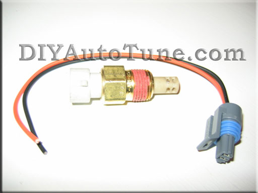
I've got this sensor:
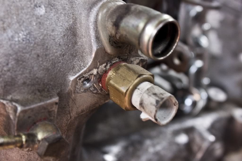
Flosho's sensor placement:
Question2: How do I hook up the brake booster ? Previously I had it directly connected to the intake manifold without the Y pipe. However now the intake manifold will sometimes be pressurized to 0.5bar. Do I need some one way valve to protect the brake booster from the 0.5bar of positive pressure?
_________________
Porsche 924 2.0 Kompressor 136.1wHp @ 5650rpm / 201.9wNm @ 3900rpm (dyno @ dp-engineering.nl) |
|
| Back to top |
|
 |
fiat22turbo

Joined: 18 Jan 2006
Posts: 4040
Location: Portland, OR
|
| Posted: Wed Jul 25, 2012 11:26 pm Post subject: |
|
|
Yep, the booster should have a one-way valve already (sometimes built into the adapter that goes in the rubber grommet on the booster itself)
The PCV valve will also need to be a one-way valve or you may pressurize the bottom end (you can also just vent this to a catch can to avoid that)
_________________
Stefan
1979 924 Carrera GTS (clone-ish)
1988 944 Turbo S (Silver Rose) |
|
| Back to top |
|
|
ideola

Joined: 01 Oct 2004
Posts: 15548
Location: Spring Lake MI
|
| Posted: Wed Jul 25, 2012 11:36 pm Post subject: |
|
|
IMO, the IAT should be as close to the head as possible, i.e. after the TB and in the intake plenum. This is how Porsche did it, and that is really the air temp you care the most about. Further upstream may not be indicative of the air temp as it's entering the head.
_________________
erstwhile owner of just about every 924 variant ever made |
|
| Back to top |
|
|
fiat22turbo
Joined: 18 Jan 2006
Posts: 4040
Location: Portland, OR
|
| Posted: Wed Jul 25, 2012 11:39 pm Post subject: |
|
|
Probably but it on runner number 4 (which tends to be the warmest) where the flat boss is for the WUR.
_________________
Stefan
1979 924 Carrera GTS (clone-ish)
1988 944 Turbo S (Silver Rose) |
|
| Back to top |
|
|
Arvidw
Joined: 20 Sep 2009
Posts: 227
Location: The Nederlands (Europe)
|
| Posted: Thu Jul 26, 2012 7:23 am Post subject: |
|
|
I'll check my brake booster for a one way valve or install one. The PCV hose will be connected to the intake of the SC so no boost will be present.
Thanks for the confirmation that placing the IAT sensor after the TB is best. I am however not so sure about placing it in the runner as it will block the airflow slightly and will be influenced by blowback caused by valve overlap.
I'm going for the same position Flosho has chosen for his sensor.
_________________
Porsche 924 2.0 Kompressor 136.1wHp @ 5650rpm / 201.9wNm @ 3900rpm (dyno @ dp-engineering.nl) |
|
| Back to top |
|
|
Raceboy

Joined: 01 Mar 2004
Posts: 2326
Location: Estonia, Europe
|
| Posted: Thu Jul 26, 2012 3:55 pm Post subject: |
|
|
I would never put IAT on the manifold itself as it is very prone to heat-soaking.
Just before throttle have been my choice so far and it works perfectly there. Porsche has put IAT in the airbox on 928's, 911's just as a reference.
_________________
'83 924 2.6 16v Turbo, 470hp
'67 911 2.4S hotrod
'90 944 S2 Cabriolet
'78 924 Carrera GT replica
'84 928 S, sold
'91 944 S2, sold
'82 924S/931 "Gulf", sold 
'84 924, turbocharged, sold.
http://www.facebook.com/vemsporsche |
|
| Back to top |
|
|
RC

Joined: 25 Mar 2007
Posts: 2636
Location: Australia
|
| Posted: Wed Aug 01, 2012 1:50 am Post subject: |
|
|
Mounting a GM IAT with brass housing in an cast aluminium heatsink, AKA manifold, is an effective way to monitor the manifold temperature.
Along with all OEM`s, I have discovered it is a poor way to get an accurate IAT reading. OK on a cold or constantly running and moving engine, perhaps like a race car. However as soon as the car is stationary in the pits, at a red light or worse case parked with the engine stopped, the manifold IAT reading will start to climb. Especially after being parked for a few minutes, or longer, the "IAT can easily reach 40 or 50*C over the actual air temp. The car will run like crap for a minute or so until the thermistor reacts and the ECU compensates. Can be tuned around to a limited degree but is far from ideal. That`s why all OEMs put the sensor in the airbox or intake ducting, even if they use plastic composite manifolds, which will be far better anyway regarding heatsoak.
First changed the GM unit over to one with a plastic housing. Was only a few degrees better since the thermistor would simply be recording the heat radiated from the aluminium heatsink. Same as a heatsink in a high end amp or any PC processor is monitored really. Ideally we want a fast reacting thermistor, no shielding or padding, mounted directly in the airflow ( away from walls and boundary layer) and far as possible from sources of retained heat. In a plastic or carbon fibre intake tract is ideal but in my case inside a silicone tube was a fair compromise. Simply clamped between the silicone hose & ally pipe with a dob of silicone sealant.
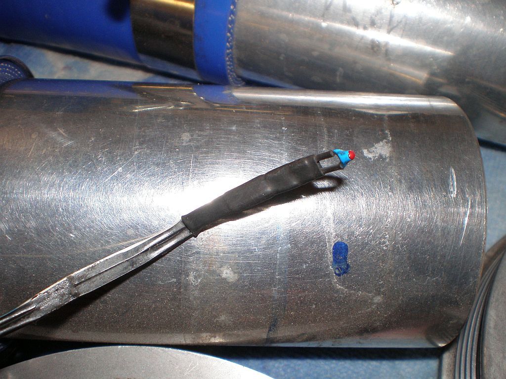
Made 2 of these basic IAT`s to measure & log post SC & pre and post IC temps. Easy to configure MS to read any thermistor accurately from the data sheet. Worked so well I used it in place of the GM unit which is just a 3/8" NPT bung now I don`t need to measure the manifold temp.
_________________
World`s quickest 924 2L slushbox
| Allan @ DTA wrote: | | I have no issue with superchargers, they are for guys who want to drive a car rather than talk about horsepower with their baseball cap on backwards |
|
|
| Back to top |
|
|
Arvidw
Joined: 20 Sep 2009
Posts: 227
Location: The Nederlands (Europe)
|
| Posted: Tue Aug 28, 2012 6:42 pm Post subject: |
|
|
Time for an update:
Started reassembling the block:


Found an oil pump with very limited wear:

And checked my new TDC marking on the flywheel:

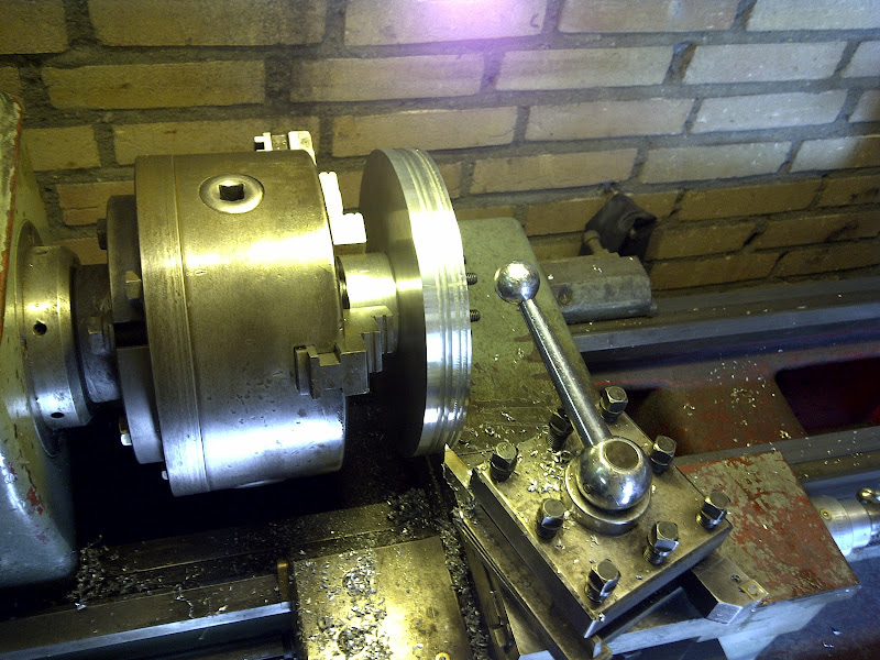
Also milled a crankshaft pulley to drive my SC. I did a couple of practice runs before finalizing the diameter of the pulley. This was a good decision as I had troubles with the stiffness of my first 40dg tool. As you can see on the second picture the right slots show severe tool vibration. This was solved with the tool shown in the picture.

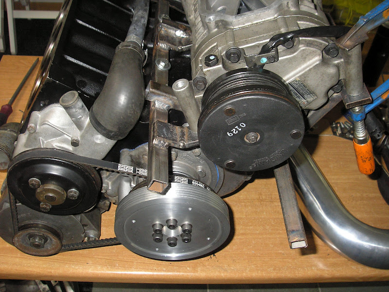
Pulley mounted on engine:


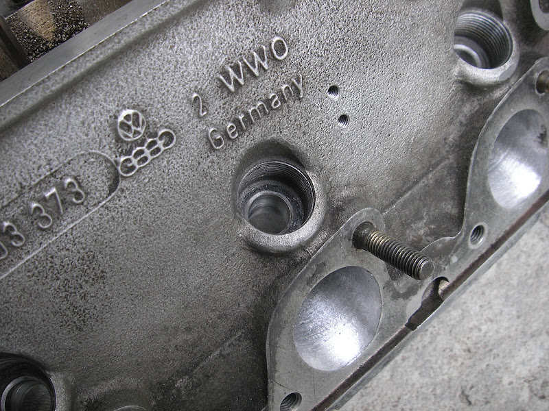
Furthermore I finalized the tuning work of the head:


I used a wooden template to match ports of head to manifold:


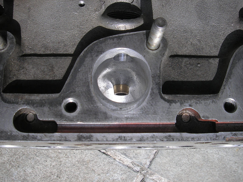
The "bumps" in the intake near the WUR mounting point have also been ground away.

It took some time to make a jig to position the head correctly underneath a milling machine to drill out the injector holes:
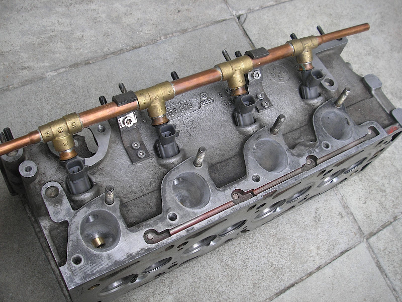
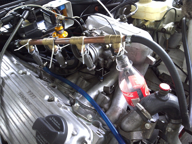
Fuel rail has been soldered and brackets constructed. The brackets are bolted directly to the head and the treads will be sealed with the correct loctite tread sealant.


A TPS sensor was added to the original 924 throttle body:


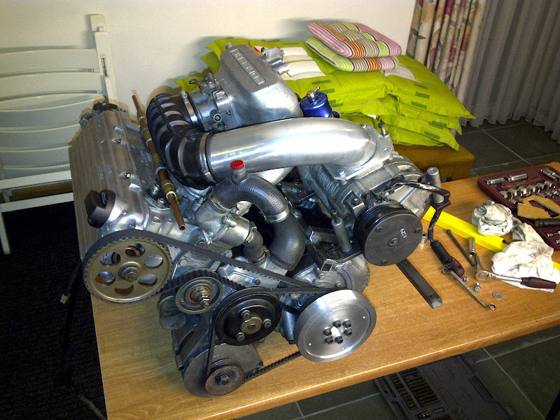
And I bought 3" (76mm) intake pipes to connect everything together. I am aware that the stock TB will pose a big flow restriction but this can easily be solved in a later stadium. My Turbosmart 2011 Vee porth BOV has also arrived:

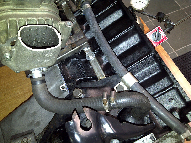
Friends from www.jeroentjetuning.nl welded a crank ventilation pipe to the intake of my supercharger. It is connected to the crank ventilation with old 924 coolant hoses.
_________________
Porsche 924 2.0 Kompressor 136.1wHp @ 5650rpm / 201.9wNm @ 3900rpm (dyno @ dp-engineering.nl) |
|
| Back to top |
|
|
CorsePerVita

Joined: 25 Jul 2008
Posts: 1992
Location: Redmond, Oregon
|
| Posted: Tue Aug 28, 2012 7:17 pm Post subject: |
|
|
I'm curious, where did you end up putting your coolant temp sensor? I have yet to find a place for mine.
Nice work by the way.
_________________
- 1977 Porsche 924 2.0 N/A (Trackday Project)
- 1979 Porsche 924 2.0 N/A (The other daily)
- 1980 Porsche 931 (Daily)
- 1987 Lamborghini Jalpa
- 1999 Ducati 900SS |
|
| Back to top |
|
|
fiat22turbo
Joined: 18 Jan 2006
Posts: 4040
Location: Portland, OR
|
| Posted: Tue Aug 28, 2012 11:30 pm Post subject: |
|
|
Put it in the stock housing on the back of the head, next to the gauge sender. Might have to bore the hole and retread it.
_________________
Stefan
1979 924 Carrera GTS (clone-ish)
1988 944 Turbo S (Silver Rose) |
|
| Back to top |
|
|
Arvidw
Joined: 20 Sep 2009
Posts: 227
Location: The Nederlands (Europe)
|
| Posted: Wed Aug 29, 2012 7:25 am Post subject: |
|
|
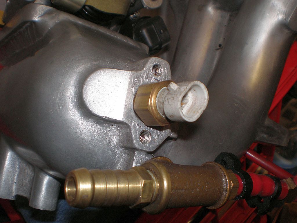
I've got it at the exact same place as fiat22turbo describes:

_________________
Porsche 924 2.0 Kompressor 136.1wHp @ 5650rpm / 201.9wNm @ 3900rpm (dyno @ dp-engineering.nl) |
|
| Back to top |
|
|
Arvidw
Joined: 20 Sep 2009
Posts: 227
Location: The Nederlands (Europe)
|
| Posted: Sun Sep 02, 2012 6:18 pm Post subject: |
|
|
Assembled the cilinderhead:


I picked the best valve springs from in total around 40 springs.

I still need a belt and belt tensioner. I suppose this will do ?

The basic shape of the pressure tube:
_________________
Porsche 924 2.0 Kompressor 136.1wHp @ 5650rpm / 201.9wNm @ 3900rpm (dyno @ dp-engineering.nl) |
|
| Back to top |
|
|
leadfoot

Joined: 11 Dec 2002
Posts: 2222
Location: gOLD cOAST Australia
|
| Posted: Fri Sep 07, 2012 7:10 pm Post subject: |
|
|
Looks great,
you know you can get an aluminium extruded fuel rail for $20 might look a little nicer?
and probably best to use a restrictor on the crank breather and a catch can before feeding it into the intake of the sc... it will also help to do the same thing to the head, use a fitting and route this to the catch can to vent gasses.
P.S crossover outlet pipe to manifold looks awesome...
Stu
_________________
1981 ROW 924 Turbo -
carbon fiber GT mish mash
LS1 conversion in progress... |
|
| Back to top |
|
|
Arvidw
Joined: 20 Sep 2009
Posts: 227
Location: The Nederlands (Europe)
|
| Posted: Thu Sep 20, 2012 7:11 am Post subject: |
|
|
@Stu, Thanks  I have to admit that the fuel rail is maby a bit too DIY however for some not very apparent reason the fuel rail extrusions are not commonly available in europe. I have to admit that the fuel rail is maby a bit too DIY however for some not very apparent reason the fuel rail extrusions are not commonly available in europe.  Some day i'll replace the DIY fuel rail for something decent looking. Some day i'll replace the DIY fuel rail for something decent looking.
I suppose the restrictor is necessary to limit the amount of oil going trough the supercharger? My original CIS setup didn't have a restrictor either although I've seen restrictors fitted as standard on early 924.
Finally the engine is in and running ! 

It is running really smooth which is fantastic and amazing as the engine was build up from second hand parts from 6 ! different engines 
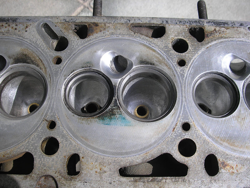
The cooling of cilinder 4 has been improved by increasing the diameter and flow in the rear coolant point. The internal diameter went up from 6 to 10mm.


I measured the injector dead time of my new injectors and also found the influence of the battery voltage on the dead time: 1.175ms dead time and 0.265ms/V. Quite a boring process but important to get it right from the start.
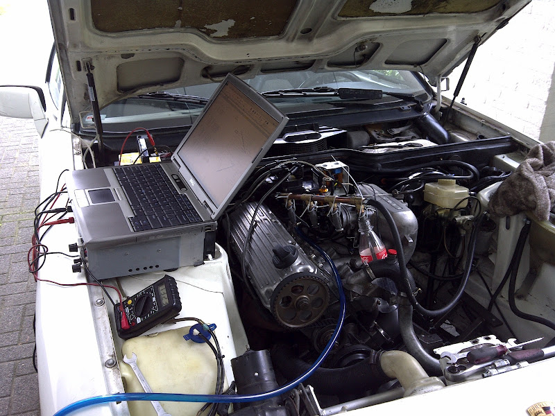
And of course a video showing the Kompressor running for the first time with the usual boost-limiting loose intake clamps.
http://youtu.be/UXzYi7wzh_8
Edit: Embedded youtube link doesn't work, therefore just an url link.
_________________
Porsche 924 2.0 Kompressor 136.1wHp @ 5650rpm / 201.9wNm @ 3900rpm (dyno @ dp-engineering.nl) |
|
| Back to top |
|
|
leadfoot
Joined: 11 Dec 2002
Posts: 2222
Location: gOLD cOAST Australia
|
| Posted: Thu Sep 20, 2012 12:15 pm Post subject: |
|
|
Looking good mate,
FYI found this RE: Clutch control
http://www.summitracing.com/search/?keyword=SUM-830452-1%20&dds=1
Its a RPM activated window switch, from the tech department it can be run off sensors or of the coil, you need to run it triggering a relay but thats a simple excercise to do... should be easy enough to configure and gives a nice digital readout.
Stu
_________________
1981 ROW 924 Turbo -
carbon fiber GT mish mash
LS1 conversion in progress... |
|
| Back to top |
|
|
|

