 |
924Board.org
Discussion Forum of 924.org
|
| View previous topic :: View next topic |
| Author |
Message |
RC

Joined: 25 Mar 2007
Posts: 2637
Location: Australia
|
 Posted: Sat Jun 02, 2012 3:06 am Post subject: CC your head & pistons for true Compression Ratio Posted: Sat Jun 02, 2012 3:06 am Post subject: CC your head & pistons for true Compression Ratio |
 |
|
WTF is your compression ratio?
Euro 9.3:1 compression ratio. USA NA 8.9:1CR. 7.5:1CR on 931S1. 8.5:1CR on 931S2, US or Euro? Pick a number. A book number that your Porsche may have at one time exited the factory with. Like a virgin, well before scores of mechanics, machine shops and PO`s have screwed around with her over the last 35 years or so.
Most of us have some idea of the term compression ratio. Your compression ratio has an ultimate affect on your maximum power output, your fuel economy and possibly the longevity of your engine under adverse conditions. Your compression ratio, your fuel, your engine design, your ignition timing, the temperature and altitude, the engine load, and especially your boost, are all interrelated. Changing any one factor will impact on the end result. Knowing your true CR is important to ensure that even a stock car is really within the "normal" range for your M/Y and can happily run the fuel grade and tune up specs at typical book value. Accurate CR will help enable the tune to be more precisely adjusted for various requirements, not necessarily power related but also perhaps economic and safe running on a cheaper lower grade gas. Measuring and calculating the CR is one of the crucial starting points to any well thought out modifications. It is so easy and quick to carry out, especially on just a single cylinder as a general indication, as a matter of course on any rebuild.
Compression ratio means just that; its a ratio, it is the ratio to which extent the combustion mixture is compressed. The term ratio is proportional and simply means the MAXIMUM TOTAL VOLUME of the combustion chamber divided by the MINIMUM COMPRESSED VOLUME. Although it is exactly the same principle with a rotary engine, for a piston engine this means the total of the volume in the cylinder AND combustion chamber at the bottom of the stroke : (to) the volume at the top of the stroke when it is compressed at it`s maximum. The static compression ratio or CR is a ratio that is easily calculated by simple maths once a few certain variables are known.
So to expand, this becomes a RATIO BETWEEN the effective displacement (swept area of the bore, essentially the area the rings contact, multiplied by the stroke), the volume of the combustion chamber in the head, the spark plug, the gasket void, the volume between the piston dome and the theoretical deck height (+/- depending if dished like 924/931 or raised dome), the volume of the clearance between piston crown/ dome (whatever is above the rings, since that is where the seal is) and the bore AND the volume of the combustion chamber in the head, the spark plug, the gasket void, the volume between the piston dome and the theoretical deck height, the volume of the clearance between piston crown and the bore.
Assuming that the accurate bore size is known, which will in reality give a larger displacement than any calculation based on piston or nominal bore diameter, the displacement can easily be calculated very accurately mathematically. The volume of the gasket void can also be mathematically derived at to small tolerances if the true compressed gasket thickness is measured or predetermined and allowance is made for any material deformation and fire/ rolled edge.
What simply can not be calculated to any degree of accuracy is the true combustion chamber volume and the true piston/ bore volume at TDC. With sophisticated software and using their own measurements, piston manufacturers may be able to give a reasonably close approximation of the expected CR using their products in a "standard" or virgin engine. Even with precise measurements of the deck height, variations in crankshaft, rod/pin/ piston alignment, and allowances calculated for every angle, radius, nook & cranny in the piston/ head/ gasket combination there still remains individual variations in the combustion chamber (piston) and/or head volume due to casting, machining and parts tolerances. Perhaps some of the more exotic 924`s were blueprinted by Porsche technicians, having every cylinder matched precisely to a determined volume, for a specific CR? IDK? What is certain though for 99% of the cars on this board is there was probably quite an actual variation straight from the factory anyway, within "normal tolerances". Then after all these years since, it is highly unlikely that there would be not be one head that had not been taken off at least once. Most likely it was at least skimmed 0.010" or 0.25mm, much more if any boost and detonation were involved. What`s more is the effect of any valve rework, any valve work whatsoever. Even a very basic manual lap with fine paste will drop a valve by a few thou at least, on a good seat. Calculate the volume displaced on a typical 40mm intake valve by lowering it just 4 thousands, 0.1mm. Multiply that by, have a guess, how many times has your head been off? That`s just a minimum, assuming of course no machine shop (or backyard butcher) has reground the valve faces and recut the valve seats. Valves will sit even deeper still if any type of multiangle seat work has been performed. So now calculate the displaced volume of a 40mm valve dropped by 0.5mm. Or on the other hand, volume will have likely decreased if oversized valves have been fitted. Although balancing chamber volume by adjusting valve height is a very old hot rod trick, still used today by those with $$$ or/or skill, it is virtually never allowed for in any "estimations". Probably because it is well accepted by all professional builders that these critical volumes are only precise when measured and actual measurement is also far more time and cost effective.
Start off with a scrap bit of acrylic/ perspex/ plexiglass, ideally 3/16 to 1/4" thick. Cut it roughly square, at least say 4" or 100mm to do a 924 bore. A piece ~125mm or 5" should do all conventional big blocks/ bores too.

Mitre the corners if you wish, may on rare occasions permit access to "in situ" jobs or around manifolds etc but not necessary. Gave it a very quick deburr of all edges by rubbing it against a wire buff wheel, but a file or abrasive paper is all it needs. Main point is that it sits dead flat in use with no high spots or protrusions, and a slightly radiused edge also helps keep blood inside fingers, this stuff can be sharp.

Drill a 3/16 or 1/4" hole about 1/2 - 3/4" in from one edge. Don`t fall for the trap of drilling a hole in the centre and later discovering that it is very difficult to
purge the air bubbles. Then using the correct tool or a large drill, carefully countersink the hole to the full depth or very close. Makes it far easier to fill and get an accurate reading.

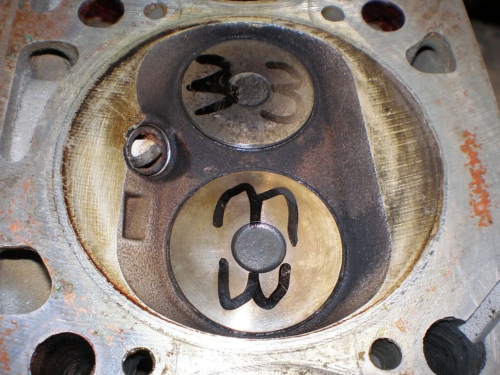
If doing a head like this example, chock it up on blocks of wood or whatever so that there is definitely a high and low end. We can use gravity & physics to make our task more fun; water runs down while air bubbles come up.
A 924 block sitting in a car with its head off is pretty common around here, and the ideal opportunity to accurately assess the lower volume of the combustion chamber. Whether the bottom end is already angled at 40* in situ, or on a lesser angle mounted on an engine stand, the hole in the plate will always need to go at the highest point.

All surfaces need to be temporarily sealed against whatever liquid medium is used. Common cheap grease or petroleum jelly (Vaseline) works well using water or alcohol. Place a very thin coating of grease around the valve faces before dropping them in. What you see in the photo is more than enough.

Apply pressure & rotate slightly to ensure a seal & squeeze out any excess grease. Clean it off flush with a rag if any appears above or around the valves. In the case of measuring the piston volume in a block, we apply grease to the side of the bore near the top and then slowly rotate the crank to raise the piston to TDC. Using a dial indicator or just feeler gauges & a straight edge helps confirm TDC and that the "0" line on the flywheel is indeed accurate.
Back to our head, plainly the spark plug hole needs to be blocked, specifically with the same plug as will be run. Even a different heat range here will result in a slightly different volume. In this instance pictured, we become aware of a problem before the plug is fully seated. After assembly the plug will simply be jutting out into the combustion chamber formed by the deeply recessed piston, however it protrudes well past the head face and will interfere with the acrylic plate.

The easiest practical method is to space the plug out using another washer or two, standard spark plug washer or in this case a copper "CIS" washer. Whatever washer, measure the compressed thickness, note it, and allow for the extra displacement in your calculations. Make sure any plug washers are already fully compressed. This is the ideal use for those old CIS washers you just kept for some odd purpose.


A very thin coat, only a finger wide is then applied around the circumference of the combustion chamber. Line up the hole in the plate with the highest point, get down to the same level and sight the high spot before plonking the plate against the grease. Push down around the edge to
ensure a good seal, it doesn`t take much.

Send the kids down to the drug store or local needle exchange for a family size pack of syringes. (joke FFS) After breaking expensive glass burettes have found that the appropriate disposable syringe is also more convenient and nearly as accurate if precision is exercised. Don`t go for the largest size unless doing a tractor or ship, get an intermediate size with more graduations for better accuracy. And a small 1-5 CC unit for the "last drop" helps too.

Take your time and first see where the 0 mark is on the device and the relative position of the graduation marks. Then overfill the syringe, invert it - point it upwards, just like all the TV doctors do. Bleed out the air bubbles while reducing the volume to whatever desired starting point, 10cc in this example.

It really doesn`t matter what you select for a measuring medium except for solvents like gas, which affects whatever grease you used. Water, coloured, alcohol substances (metho, ethanol, whiskey), expensive bottles of special CC fluid from the local FLAPS, practically whatever is fine.

Carefully empty the syringe while watching the level rise. Basic rocket science techniques apply here, slow, accurate, keep records, progress to smaller and finer graduated syringes as the level gets close. We want it level with the lower face of the plate, before it starts to rise out the hole. Then stop and take count of how much in total WENT IN.

In out example here, the level rose to the top of the plate at the bottom of the countersunk hole precisely as the second syringe was fully emptied. Not a common occurrence but it does happen sometimes. This makes 20.0 cc in the chamber. Then we must allow for the copper washers we used on the spark plug to space it out. Doing so allowed more fluid to enter the chamber space so we must deduct the displacement of the nominal 14mm plug thread times the thickness of two washers. For practical purposes we can assume the washers will compress 0.02mm (~1 thou) and use the 1.3mm thickness. Two of these displace 0.40cc. Therefore our chamber volume is 20.0 - 0.4 = 19.6cc.
That`s not a magic number, it is a basic measurement we need for our compression ratio calculations to be accurate. Like any calculation, the end result is fully dependent on the accuracy of the input data.
_________________
World`s quickest 924 2L slushbox
| Allan @ DTA wrote: | | I have no issue with superchargers, they are for guys who want to drive a car rather than talk about horsepower with their baseball cap on backwards |
|
|
| Back to top |
|
 |
ideola

Joined: 01 Oct 2004
Posts: 15550
Location: Spring Lake MI
|
| Posted: Sat Jun 02, 2012 4:31 am Post subject: |
|
|
Great write up and pix, thanks!
Just to point out, the 19.6cc number in this case is based on a head that is beyond the wear limit. As the head is resurfaced, additional combustion chamber volume will be removed, so a head that is within the wear limit will have a greater volume than the example in this write-up, which will contribute to the overall combustion chamber volume, and therefore reduce the overall CR.
For what it's worth, the difference in CR from the 21.5cc measured by CBass (several years ago, head wear limit not noted) and the 19.6cc measured by RC has the following effect on CR:
US S1: 7.5:1 CR increases to 7.666:1
US S2: 8.0:1 CR increases to 8.193:1
ROW: 8.5:1 CR increases to 8.725:1
For you normally aspirated guys, the above work is not necessary (or possible), as the NA head is completely flat, with essentially zero volume in the head.
Overall CR is calculated based on the entire combustion chamber volume, which consists of the following:
volume in the head (Vh)
volume in the gasket (Vg)
volume in the cylinder (Vc)
volume in the piston (Vp)
So total combustion chamber volume (Vt) = Vh + Vg + Vc + Vp
For example on a bone stock ROW 931, it works out as follows:
Vh = 21.5cc (or somewhere thereabouts; measure for accuracy)
Vg = 7.106cc (calculated based on a stock 88mm gasket bore at the OEM .046" thickness; .046" = 1.168mm)
Vc = 0cc (an unmolested 931 short block has the piston crown flush with the deck, so therefore ZERO cc in the cylinder itself)
Vp = 37.5cc
Vt = 66.106cc (21.5 + 7.106 + 0 + 37.5)
The formula for calculating CR is: ((Pi/4)*B^2*S/1000)+Vt)/Vt
Where B = the cylinder bore, and S = the stroke
Using stock figures of B = 86.5mm and S = 84.4mm, you can see that the CR comes out to exactly 8.5:1, which is correct for ROW 931 setup.
_________________
erstwhile owner of just about every 924 variant ever made |
|
| Back to top |
|
|
ideola
Joined: 01 Oct 2004
Posts: 15550
Location: Spring Lake MI
|
| Posted: Sat Jun 02, 2012 4:39 am Post subject: |
|
|
Also, for what it's worth, here are the piston dish volumes for stock pistons:
US S1 931: 47.700cc (7.5:1 CR)
US S2 931: 42.250cc (8.0:1 CR)
ROW 931: 37.500cc (8.5:1 CR)
80-on US NA: 26cc (9.0:1 CR)
ROW NA: 24cc (9.3:1 CR)
I don't know the volume of the earlier US pistons off hand, but solving for X, we can deduce the following:
77.5-79 US NA: ~30.8cc (8.5:1 CR)
76-77.5 US NA: ~35cc (8.0:1 CR)
_________________
erstwhile owner of just about every 924 variant ever made |
|
| Back to top |
|
|
|
|
You cannot post new topics in this forum
You cannot reply to topics in this forum
You cannot edit your posts in this forum
You cannot delete your posts in this forum
You cannot vote in polls in this forum
|
Powered by phpBB © 2001, 2005 phpBB Group
|

