 |
924Board.org
Discussion Forum of 924.org
|
| View previous topic :: View next topic |
| Author |
Message |
ideola

Joined: 01 Oct 2004
Posts: 15550
Location: Spring Lake MI
|
 Posted: Tue Feb 12, 2008 12:11 pm Post subject: Posted: Tue Feb 12, 2008 12:11 pm Post subject: |
 |
|
So after much time and consideration, I've actually made some progress on the intake modification concept. I considered PowerGTOGuy's ITB approach, as well as picking up Bass GT's old ITB setup, but both options were in the $1K + range, with the added disadvantage of having to move stuff around in the engine compartment, most notably the alternator, as well as the added expense of having to convert immediately to EFI.
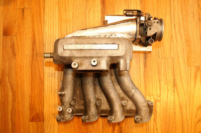
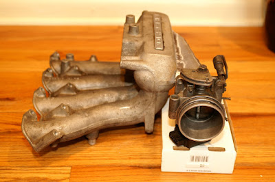
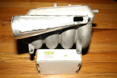
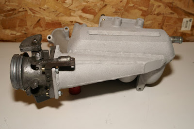
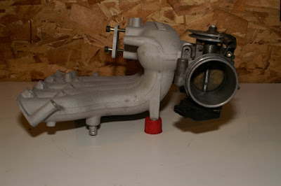
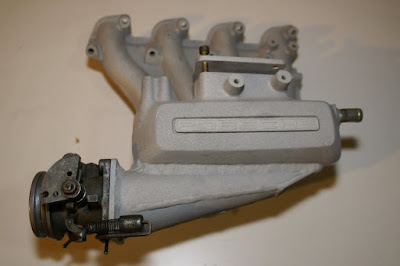
To refresh everyone's memory, my goal was to create a manifold that would not require me to re-engineer the main plenum & runner designs, would require minimal (if any) relocation of other engine bay components, and would orient the throttle body for a direct, short run from a FMIC. Here are the preliminary results:
 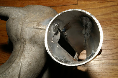
After reading Todd's post on the diffuser concept, I did some more research and validated the idea of using a secondary diffuser plenum to evenly distribute the airflow across the four runners (as the air approaches the rear of the diffuser, it is theoretically accelerated, thereby delivering relatively equal airflow across the interface port).
I strongly considered using the N/A manifold due to its shorter runners, which would give better clearance for routing the TB into the manifold from the driver side. However, this has the adverse affect of positioning the TB in direct interference with the alternator.
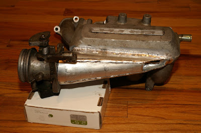
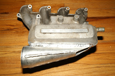
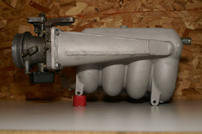
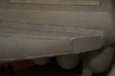
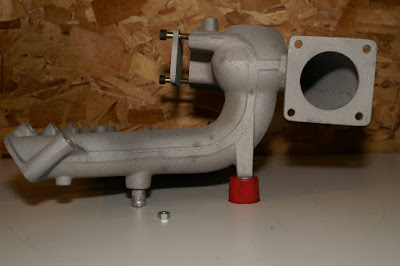
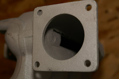
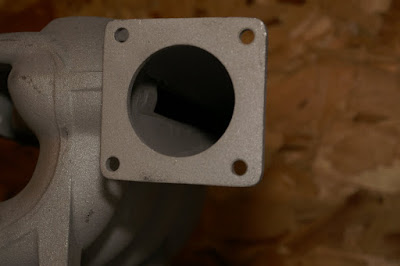
The current iteration uses a Series I intake manifold. We cut an interface port 170mm long by 18mm high, which keeps the diffuser opening larger than the TB opening (3060 sq. mm. for the former vs. 2826 sq. mm. for the latter) so as not to create a negative pressure differential. The top of the interface port was cut directly along the mold line on the intake.
The diffuser was made out of a piece of 2.5" diameter aluminum tubing. A cone was fashioned by cutting four longitudinal triangular shapes out of the tube, bending the resulting "wings" together and welding the seams, resulting in a small-end opening about the size of a quarter. The large end opening will receive a 1/8" mounting plate for the TB. In order to provide better clearance between the rear of intake manifold and the brake booster, the small end of the diffuser was cut off at a more acute angle and will be sealed.
A matching interface port was then cut into the diffuser, which was subsequently welded onto the intake manifold. As noted above, the top of the interface port is directly along the molding seam on the manifold. It could not be any higher, because it would place the TB too high at its more forward location, potentially causing the throttle linkage to bind on the hood (bonnet) when closed.
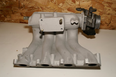
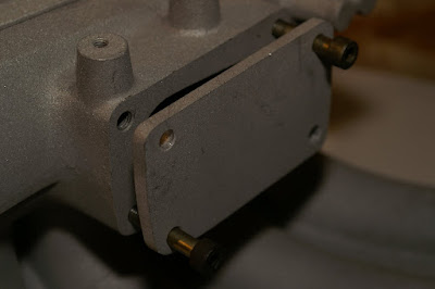
The resulting configuration places the TB directly between the alternator and the coolant tank in their stock locations, and in precisely the correct orientation to attach the charge tube from a FMIC. The original TB mounting location will be sealed with a bolt-on block-off plate, which will subsequently be engineered to receive one or more fuel enrichment injectors that will be driven by a rising rate fuel pressure regulator. The ONLY engine bay mod required will be to re-orient some of the plumbing and to remove the rear sensor on the brake master cylinder by converting it over to the earlier style sensor contained within the reservoir cap (I have a spare from one of my 931 donor cars).
I don't want to launch another EFI-CIS war / debate. However, it is worth noting that I have validated with multiple sources the rising-rate FPR fuel enrichment approach as a suitable way of adjuncting the stock CIS system. In fact, this is precisely how at least one 80s vintage 924 GTx variant was configured (don't remember now which one, but there is an extensive discussion of it over on Rennlist). It is also worth noting that positioning the injectors to spray TOWARD the airflow is a technique espoused by the esteemed Corky Bell in "Maximum Boost". I know this approach is not as fine-tunable or efficient as EFI. But I also believe it will work just fine in the short term. It will also cost about 1/4 of a complete EFI conversion.
To complete the intake manifold (now that I have verified test fitment), the remaining welds will be made, the TB adapter plate will be added, everything will be sandblasted and polished, and she'll be ready for paint / powder coat. Should be done within a couple of weeks.
Total cost: <$400 for materials and welding (not including the fuel enrichment setup, of course).
_________________
erstwhile owner of just about every 924 variant ever made
Last edited by ideola on Fri Jul 17, 2009 11:25 pm; edited 1 time in total |
|
| Back to top |
|
 |
endwrench

Joined: 07 Dec 2002
Posts: 1631
Location: Victor, Montana
|
| Posted: Tue Feb 12, 2008 2:34 pm Post subject: |
|
|
Nice excecution! I still like the whole concept. More than one way to skin a cat.
Todd
_________________
'79 924NA. Rebuilt 9.5:1, MSDS header, Mega Squirt Injection, MJLJ-EDIS Ignition, 1.6L Whipple Charger and Intercooler, 10lbs Boost, 944 Trans, Custom HD Clutch.
"simsport" said....superchargers are better than turbos its official!.... |
|
| Back to top |
|
|
Rasta Monsta

Joined: 12 Jul 2006
Posts: 11733
Location: PacNW
|
| Posted: Tue Feb 12, 2008 2:49 pm Post subject: |
|
|
Me likie. I think it's important to preserve runner volume.
_________________
Toofah King Bad
- WeiBe (1987 924S 2.5t) - 931 S3
|
|
| Back to top |
|
|
leadfoot

Joined: 11 Dec 2002
Posts: 2222
Location: gOLD cOAST Australia
|
| Posted: Tue Feb 12, 2008 4:18 pm Post subject: |
|
|
Make sure you don't hit the bonnet with the throttle body. Consider also going with a thicker mounting plate for the throttle as you will get better clamping force and be less likely to blow out a gasket.
Looks good though...
leadfoot
_________________
1981 ROW 924 Turbo -
carbon fiber GT mish mash
LS1 conversion in progress... |
|
| Back to top |
|
|
Peter_in_AU

Joined: 29 Jul 2001
Posts: 2743
Location: Sydney, Australia
|
| Posted: Tue Feb 12, 2008 8:32 pm Post subject: |
|
|
Wow! That is very motivating.
_________________
1979 924 (Gone to a better place)
1974 Lotus 7 S4 "Big Valve" Twin-cam (waiting)
1982 924 (As featured on Wikipedia)
Learn to love your multimeter and may the search be with you |
|
| Back to top |
|
|
ideola
Joined: 01 Oct 2004
Posts: 15550
Location: Spring Lake MI
|
| Posted: Tue Feb 12, 2008 10:52 pm Post subject: |
|
|
| Rasta Monsta wrote: | | Me likie. I think it's important to preserve runner volume. |
Yeah, after thinking long and hard on this one, reading and re-reading several posts here and elsewhere on intake designs, and also hearing experiences of those who have gone before me (like Nick), I became less and less comfortable with the idea of a completely custom fabricated plenum and runners. There's a reason those runners have that funky shape to them. Also, after reading the theory on diffuser plenums and seeing example after example on modern cars, it just made sense to me that there was no reason to get rid of the stock manifold design. It also seemed reasonable to assume that a diffuser plenum would actually be an improvement (in terms of air distribution across the runners) over the original TB placement, which directs air into the center at a 90 degree angle rather than more evenly distributed across the primary plenum.
I'm excited by the results and the fact that I will have very little re-configuration to do under the hood to accommodate this setup.
| leadfoot wrote: | | Make sure you don't hit the bonnet with the throttle body. Consider also going with a thicker mounting plate for the throttle as you will get better clamping force and be less likely to blow out a gasket. |
Bonnet / Hood clearance is definitely a concern. I looked at this very carefully, and in fact, this was one of the more challenging aspects to figure out. My test fitments of the nearly-complete manifold indicate that it won't be a problem. I won't be certain until everything's assembled and installed in the actual chassis. However, a couple of things I noted and took care to observe: first, the top surface of the plenum itself is not parallel to the ground, but rather is on a slight angle, parallel to the bonnet / hood. By attaching the diffuser no higher than the top edge of the mold seam on the original intake, the diffuser is mounted low enough, and also maintains the same angle as the top of the original plenum. In so doing, the TB linkage assembly in its planned orientation will be roughly even with and no higher than top of the coolant reservoir cap, which is the highest object in that vicinity. I measured this all very carefully using measuring tape and a piece of 2x4 to check the plane at that location in the engine bay.
As a fall back plan, if the TB linkage does interfere with the bonnet / hood, I will either mount the TB 90 degrees rotated, or I will install a conveniently located hood scoop on the driver side to give the extra clearance and also provide additional ducting into the engine bay. I still have to sort out how to mount the throttle linkage anyway, so these options give me some alternatives in a worst case scenario.
Thanks for the tip on the thickness of the mounting plate. There's plenty of room to play with front-to-back, so perhaps I'll just go with a 1/4" or 3/8" thickness. I based my original measurement on the thickness of the metal on the TB itself.
One other thing worth noting: I was originally planning to install a larger mounting plate that would accommodate a 65mm Mustang 5.0 TB. The plan was to have slotted mounting holes on the TB bracket (at the end of the diffuser). Since the Series II TB and the Mustang TB are both square, the slotted holes would have accommodated both, and would have provided an upgrade path for later conversion to EFI. The unfortunate issue is that the linkage assembly on the Series II TB will not allow for a mounting plate large enough for the Mustang TB due to the way it hangs over the edge of the TB. When it comes time for that modification, I may end up having to cut off the old mounting plate and attach a new one. The other alternative will be to make up a new manifold based on this design, but perfecting any flaws that I might discover along the way. I have a few more intakes floating around that could be used as donors.
_________________
erstwhile owner of just about every 924 variant ever made |
|
| Back to top |
|
|
ideola
Joined: 01 Oct 2004
Posts: 15550
Location: Spring Lake MI
|
| Posted: Wed Feb 13, 2008 12:38 am Post subject: |
|
|
BTW, here is the link to the aforementioned Rennlist thread.
_________________
erstwhile owner of just about every 924 variant ever made |
|
| Back to top |
|
|
john h

Joined: 06 Nov 2002
Posts: 827
Location: Wellington New Zealand
|
| Posted: Wed Feb 13, 2008 2:49 pm Post subject: |
|
|
| ideola wrote: |
I strongly considered using the N/A manifold due to its shorter runners, which would give better clearance for routing the TB into the manifold from the driver side. However, this has the adverse affect of positioning the TB in direct interference with the alternator.
|
I wouldn't consider the N/A manifold unless you want to carry out a whole heap of extra cutting and welding. The N/A has slighlty different port spacing and also the mounting holes for the manifold to head are also spaced differently - I had thought about that route myself and tried to fit an old N/A manifold to the spare turbo motor - don't fit - so continue down your cuurent route using the turbo manifold.
_________________
Remember a Porsche is not just for Christmas,
if you take it to pieces slowly it can provide anguish all year long! |
|
| Back to top |
|
|
leadfoot
Joined: 11 Dec 2002
Posts: 2222
Location: gOLD cOAST Australia
|
| Posted: Fri Feb 15, 2008 4:05 pm Post subject: |
|
|
I was just about to suggest rotation, for the linkage, attach a small angle piece about 10/15cm away from the throttl on the side of the plenum and drill a hole in it to accomodate the cable. The cable should have to nuts that sit on either side of the hole to fix the cable.
You can get end pieces for the cable that have a screw in them too so if you need to adjust the length of the cable you can.
I ended up using a 951 cable as it was about 30cm longer than the 924 cable.
I do believe a 944 which is somewhere inbetween these length would work for you application.
Consider a throttle that has the capabilities for air bypass solenoid too.
Leadfoot
_________________
1981 ROW 924 Turbo -
carbon fiber GT mish mash
LS1 conversion in progress... |
|
| Back to top |
|
|
ideola
Joined: 01 Oct 2004
Posts: 15550
Location: Spring Lake MI
|
| Posted: Sat Feb 16, 2008 12:13 am Post subject: |
|
|
Leadfoot, thanks for the tips on the throttle linkage stuff. I'm also wondering if I could just rig up an angle bracket that mounts directly to the (to-be-added) throttle plate itself, rather than having to attach it to the plenum...
| leadfoot wrote: | | Consider a throttle that has the capabilities for air bypass solenoid too. |
Could you elaborate on that? Specifically, what is the purpose of the air bypass solenoid, and do you know of any TBs with a 60-65mm throat that would meet the criteria? I am planning to take the intake back to my fabricator this weekend, so if I need to accommodate a different bolt pattern for the TB mounting plate, I'll need to know ASAP.
| john h wrote: | | I wouldn't consider the N/A manifold... |
John, thanks for the confirmation...when I started looking at this, I decided that the NA intake would be a last resort because I identified fitment issues, plus I was concerned about the runner length.
_________________
erstwhile owner of just about every 924 variant ever made |
|
| Back to top |
|
|
leadfoot
Joined: 11 Dec 2002
Posts: 2222
Location: gOLD cOAST Australia
|
| Posted: Mon Feb 18, 2008 12:55 pm Post subject: |
|
|
The stock engine uses the Aux Air Valve i.e bypasses the trottle and allows more air at start up when you have a cold engine. This is the item to replace if your ECU allows air bypass control.
There will be one of two systems generally used
1. stepper motor - and are generally bolted to the body
2. pwm solenoid - most are mounted remotely
Most stepper motors have two speeds, fast or slow.
PWM alows a much finer control and has the abilit to adjust speeds from really fast to really slow and anywhere inbetween.
Both will adjust air volume
Ford explorer I believe has a 63mm diameter. just saves on drilling holes and spending money on fittings. I think it might also have a built in TPS like mine.
As for the linkage, as long as the cam is round that shouldn't be an issue. Mine was more oval and pulled at an angle so I had it mounted further back to alleviate any rubbing of the cable.
Stuart
_________________
1981 ROW 924 Turbo -
carbon fiber GT mish mash
LS1 conversion in progress... |
|
| Back to top |
|
|
ideola
Joined: 01 Oct 2004
Posts: 15550
Location: Spring Lake MI
|
| Posted: Fri Mar 07, 2008 1:18 pm Post subject: |
|
|
All ready for powder-coating 
_________________
erstwhile owner of just about every 924 variant ever made
Last edited by ideola on Fri Jul 17, 2009 11:28 pm; edited 1 time in total |
|
| Back to top |
|
|
tuurbo

Joined: 08 Aug 2007
Posts: 1446
Location: East Windsor, New Jersey
|
| Posted: Fri Mar 07, 2008 2:30 pm Post subject: |
|
|
| Pretty nice - was that walnut blasted or plastic bead blasted or what? How'd ya clean it up? |
|
| Back to top |
|
|
ideola
Joined: 01 Oct 2004
Posts: 15550
Location: Spring Lake MI
|
| Posted: Sat Mar 08, 2008 12:41 am Post subject: |
|
|
I think he used plastic media to clean things up...
_________________
erstwhile owner of just about every 924 variant ever made |
|
| Back to top |
|
|
bass gt

Joined: 02 Dec 2004
Posts: 971
Location: Johannesburg for now!!
|
| Posted: Sat Mar 08, 2008 6:18 pm Post subject: |
|
|
Dan,
Great work!! What percentage reduction have you used over the length of the diffusser? Is there an ideal figure for this, as i am thinking down this route as well 
Steve
_________________
Front Wheel Drive is the Devil's work. |
|
| Back to top |
|
|
|
|
You cannot post new topics in this forum
You cannot reply to topics in this forum
You cannot edit your posts in this forum
You cannot delete your posts in this forum
You cannot vote in polls in this forum
|
Powered by phpBB © 2001, 2005 phpBB Group
|

